Instruction Manual
D103175X012
GX Valve and Actuator
July 2017
6
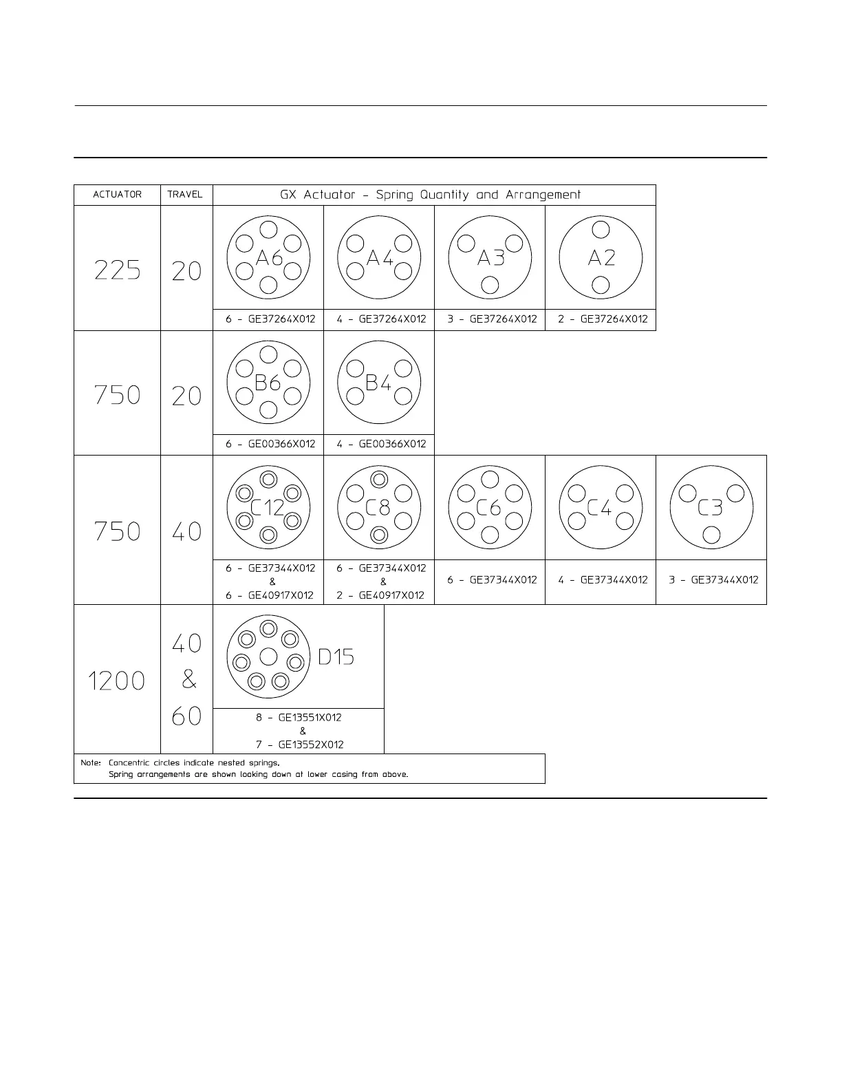
Figure 3. Spring Configuration
GG00398-B
6. Remove the short actuator casing cap screws and hex nuts (keys 17 and 18) first. Once these have been removed
from the actuator assembly, carefully remove the long actuator cap screws and hex nuts (keys 16 and 18),
alternating between them to gradually release the spring energy (compression).
7. Remove the upper diaphragm casing (key 9) and the actuator springs (key 12 and/or 82).
8. Lift off the actuator stem/diaphragm assembly (includes keys 22, 11, 10, 14, 13, 109, and 15) and remove the cap
screw (key 14), actuator spacer (key 13), actuator rod (key 22), and washer (key 15).
9. Replace the diaphragm (key 10), diaphragm O-ring (key 109), actuator rod bushing (key 19), and actuator rod seal
(key 20), as needed.