SPECIFICATIONS
(Continued)
CAPtUne
PAU
O
axes
tecsdarivaceitindadoessGenrenesdeseatartoneedes
1.5dB
Alternate
Channel
Selectivity(+400kKHz)
oo...
55dB
Image
Response
Ratio
.........ccecccceccccceecceesceseseeseeeeeaes
114dB
Spurious
Response
Ratio
...............cccccccccecccaccassesecseeeeeees
87dB
IF
RESPONSES
Ratioy...scsccsselscseviscicesieeciniievolsnceasdacecadeseoue
110dB
AM
Suppression
Ratio
............
cee
cceecccccescecccceceeccueescees
55dB
Total
Harmonic
Distortion
at
50dB
Quieting
WROTE
A
edit
rele
i8
a
2h
ctiapeee,
trata
uae
Seciadavuameeeeane
0.2%
Stereo
.........
bbs
ralacioowietuaire
debe
in
Seda
ccechate
tarertoaens
0.3%
Total
Harmonic
Distortion
at
65dBf
Monaural
(100HZ/1kKHZ/6kKHZ)
...............000008
0.3/0.3/0.4%
Stereo
(100HZ/1KHZ/6KHZ)
o.oo
eee
eeee
0.4/0.4/0.5%
Stereo
Separation
(1OOHZ/1kKHZ/10KHZ)
ooo
eee
ccceeeceseeeeeeee
40/40/30dB
Sub-Carrier
Rejection
(19kKH2/38KHZ)
..........:.cccceseee.
30/50dB
Audio
Frequency
Response
(QO
Z
rs
VO
KIAZ
cies
hae
es
snacuelet
ve
ta
lawern
ended
ea
startin
+3.0dB
AM
SECTION
Usable
Sensitivity
...............ccccccsccssssccseccccsecccusevecesess
600uV/m
MEIECUVINY,
soicteari
cocicecsnatecs
ccd
cactitede
edict
eaters
Geeinewonia
35dB
Signal-to-Noise
Ratio
..........cccccseessesssssssccssccseccseseessesns
55dB
Image
Response
Ratio
............cccccsesesescccccccccecesaccevecseecess
38dB
He
FROSDONSOFAUO:
a
ceceicresrency.c
tra
scss
sa
iuledelentieten,
oaeiee
Suokas
60dB
GENERAL
Power
Requirement
...........::cccsssscesssseceeccccssusceeeserees
AC
220V
(50Hz)
400
Watts
AC
Outlet(Switched)
..........cccccccceccccecccssssessccccecccesessceeereeseeseece
3
Dimensions
(WxHxD)
..........00.c
eee
ce
eeee
440
x
146
x
340mm
Weight
(Approximate)
0.0.0...
eececcccccccccsecsseceuececeeseecees
9.9kg
—
Specifications
and
design
are
subject
to
change
without
notice.
—
POWER
AMPLIFIER
ADJUSTMENT
BEFORE
ADJUSTMENT
Unplug
the
AC
power
cord
and
set
the
front
pane!
controls
as
follows:
@
Power
Switch
to
OFF
position.
Set
the
SPEAKERS
Switch
to
the
OFF
position.
Turn
the
MASTER
VOLUME
Control
to
minimum.
IDLING
CURRENT
ADJUSTMENT
IDLING
CURRENT
ADJUSTMENT
VR101/VR102
(on
the
Main
P.C.Board)
setting
to
mechanical
center
position.
Connect
the
AC
power
cord
and
Power
Switch
to
the
ON
position.
This
adjustment
is
very
sensitive
to
changes
in
ambient
temperature.
Allow
set
to
operate
for
2
minutes
before
attempting
this
alignment.
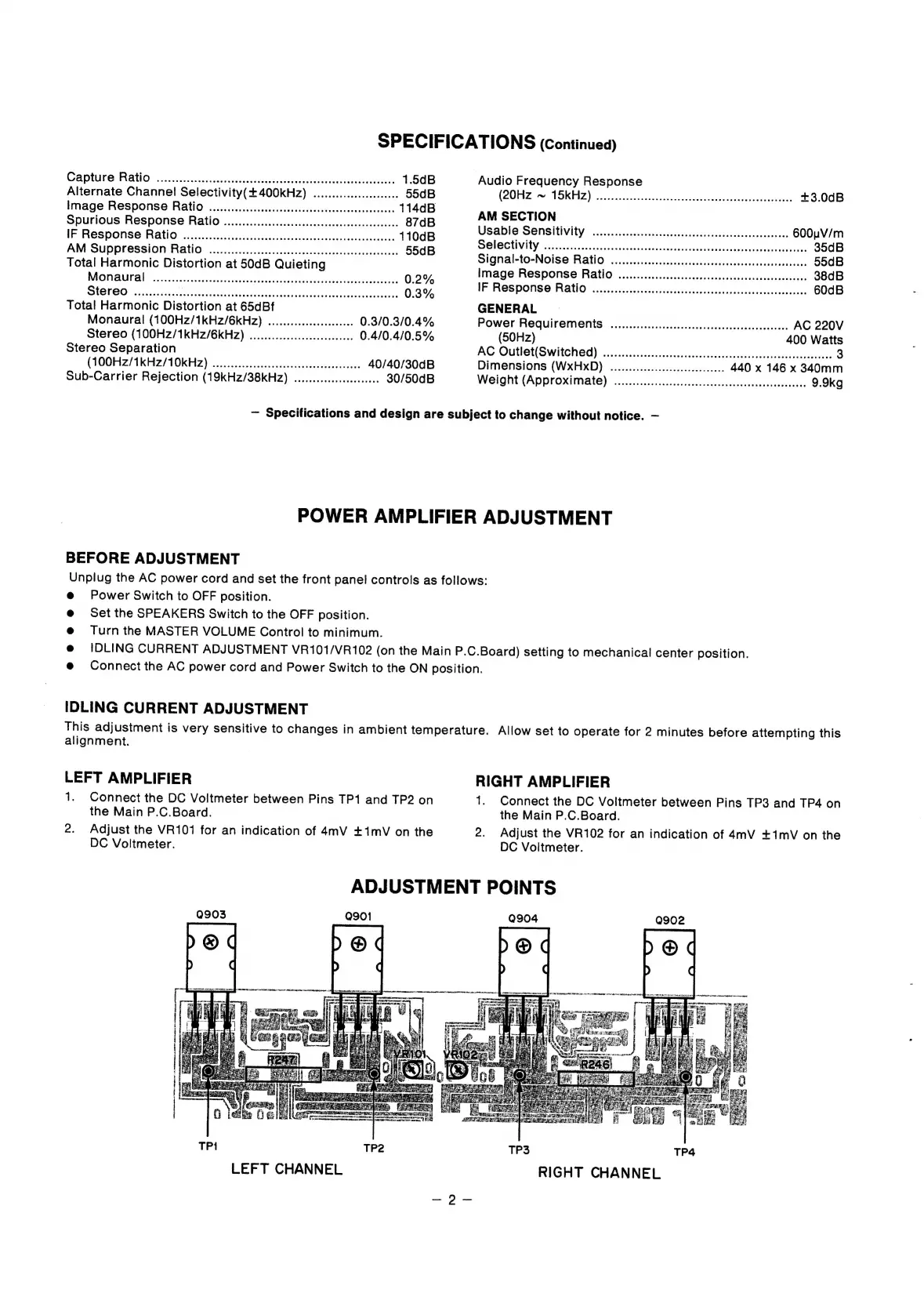
LEFT
AMPLIFIER
1.
Connect
the
DC
Voltmeter
between
Pins
TP1
and
TP2
on
the
Main
P.C.Board.
2.
Adjust
the
VR101
for
an
indication
of
4mV
+1mV
on
the
DC
Voltmeter.
RIGHT
AMPLIFIER
1.
Connect
the
DC
Voltmeter
between
Pins
TP3
and
TP4
on
the
Main
P.C.Board.
2.
Adjust
the
VR102
for
an
indication
of
4mV
+1mvV
on
the
DC
Voltmeter.
ADJUSTMENT
POINTS
LEFT
CHANNEL
RIGHT
CHANNEL


 To Next Page