Type 1008
2
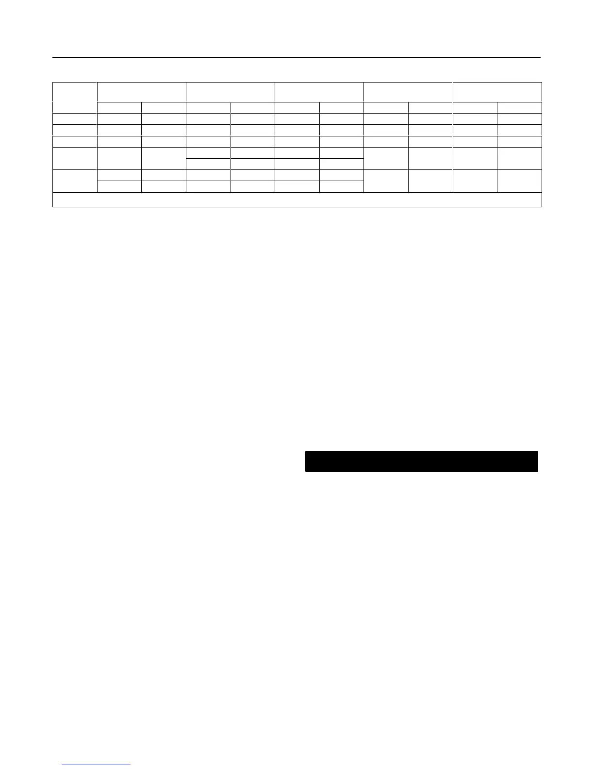
Table 1. Specifications
SIZE
YOKE BOSS
DIAMETER
STEM DIAMETER MAXIMUM STEM LOAD MAXIMUM TRAVEL
APPROXIMATE
WEIGHT
Inches mm Inches mm Pounds N Inches mm Pounds kg
30 2-1/8 54 3/8 10 1650
(1)
7340 3/4 19 15 6.8
40 2-13/16 71 1/2 13 2950
(1)
13,122 2 51 35 15.9
50 3-9/16 90 3/4 19 6650
(1)
29,581 4 102 45 20.4
1 25 11,250
(1)
50,042
80 5 127
1-1/4 32 17,000
(1,2)
75,620
3 76 100 45.4
5 127 1-1/4 32 17,000
(1,2)
75,620
100
7 178 2 51 56,000
(1,2)
251,004
4 102 150 68.0
1. For S31600 (316 stainless steel) stems at 100_F (38_C).
2. Actuator limit.
Specifications
Refer to table 1 for Specifications of the Type 1008
handwheel actuator. Refer to the actuator nameplate
for information about a specific actuator.
Installation
The Type 1008 handwheel actuator can be installed
horizontally, vertically, or at any orientation in be-
tween. However, if supplied with a Tejax position indi-
cator (see figure 6), the actuator must be installed in a
horizontal position.
When an actuator and valve body are shipped togeth-
er as a control valve assembly, the actuator is normal-
ly mounted on the valve. Follow the valve body
instructions when installing the control valve in the
pipeline. If the actuator is shipped separately or if it is
necessary to mount the actuator on the valve, perform
the Actuator Mounting procedures.
Actuator Mounting
Key numbers refer to figure 2 for size 30, figure 3 for
sizes 40 and 50, figure 4 for size 80 or figure 5 for size
100.
1. Place the actuator on the body bonnet and tighten
the yoke locknut or the actuator mounting hex nuts.
2. Ensure the valve plug is on its seat.
3. Adjust the travel indicator scale (key 27) so that the
two screws (key 19) are centered in the slots.
4. Screw the hex nuts (key 29) onto the valve plug
stem and place the travel indicator disk (key 20) onto
the stem above the hex nuts. Adjust the nuts until the
travel indicator disk (key 20) points to the closed posi-
tion on the scale.
5. Temporarily connect the valve plug stem to the
stem connector assembly (key 24) and tighten the cap
screws into the stem connector.
6. Use the handwheel (key 28) to move the valve plug
into the fully open position, as indicated by the travel
indicator disk (key 20) on the travel indicator scale
(key 27).
7. Remove the stem connector assembly (key 24).
8. Size 30: Turn the handwheel (key 28) counter-
clockwise until the stem connector assembly (key 24)
almost touches the top of the yoke;
Sizes 40, 50, and 80: Turn the handwheel (key 28)
counterclockwise as far as it will go;
Size 100: Turn the handwheel (key 28) counterclock-
wise (for push-down-to-close valves) or clockwise (for
push-down-to-open valves) as far as it will go.
CAUTION
Incomplete engagement of both valve
stem and stem screw assembly (key 38)
or size 100 power screw (key 5) in the
stem connector can result in stripped
threads or improper operation. Be sure
that the length of each stem clamped in
the stem connector is equal to or great-
er than the diameter of that stem.
9. Connect the valve plug stem to the stem connector
assembly (key 24). Ensure that the bottom of the stem
connector is touching or nearly touching the travel indi-
cator disk (key 20). Tighten the stem connector (key
24) cap screws and lock the hex nuts (key 29) against
the travel indicator disk (key 20) and stem connector.
10. Rotate the handwheel until the valve plug seats.
Adjust the travel indicator scale (key 27) with two
screws (key 19) so that the travel indicator disk (key
20) points to the closed position on the scale. Tighten
the two screws.
 Loading...


