8
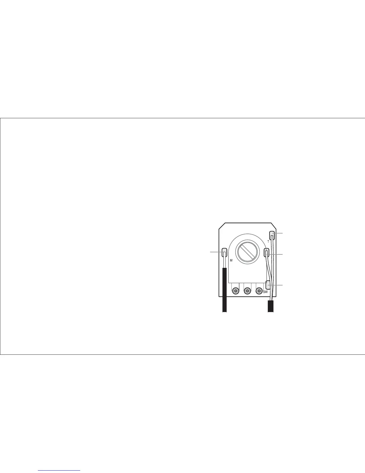
3. Solder the magnetic pickup hot wire to the circuit board.
The pad for the hot wire is located on the same side of the board as the volume
pot. This pad, labeled “M,” is on the left edge of the board, ¾” (19mm) from the
bottom of the board. A common system ground is located on the opposite side
of the board, on a second pad marked “G,” adjacent to the piezo ground. Since
there is room for only one wire on this pad, we suggest that you tie all grounds to
the body of the magnetic volume pot, and run a jumper wire to the ground pad
on the circuit board.
Note: If you install the Powerchip
with active magnetic pickups (such
as EMG), the Powerchip and the
active pickups will share the same
battery. Connect the positive battery
wire from the magnetics to the +9V
pad on the Powerchip. Connect
the negative battery wire from the
magnetics to terminal #1 on the
9-pin jack.
Output (Tip)
Output (Ring)
3-Position
Switch (Optional)
Magnetic In