9
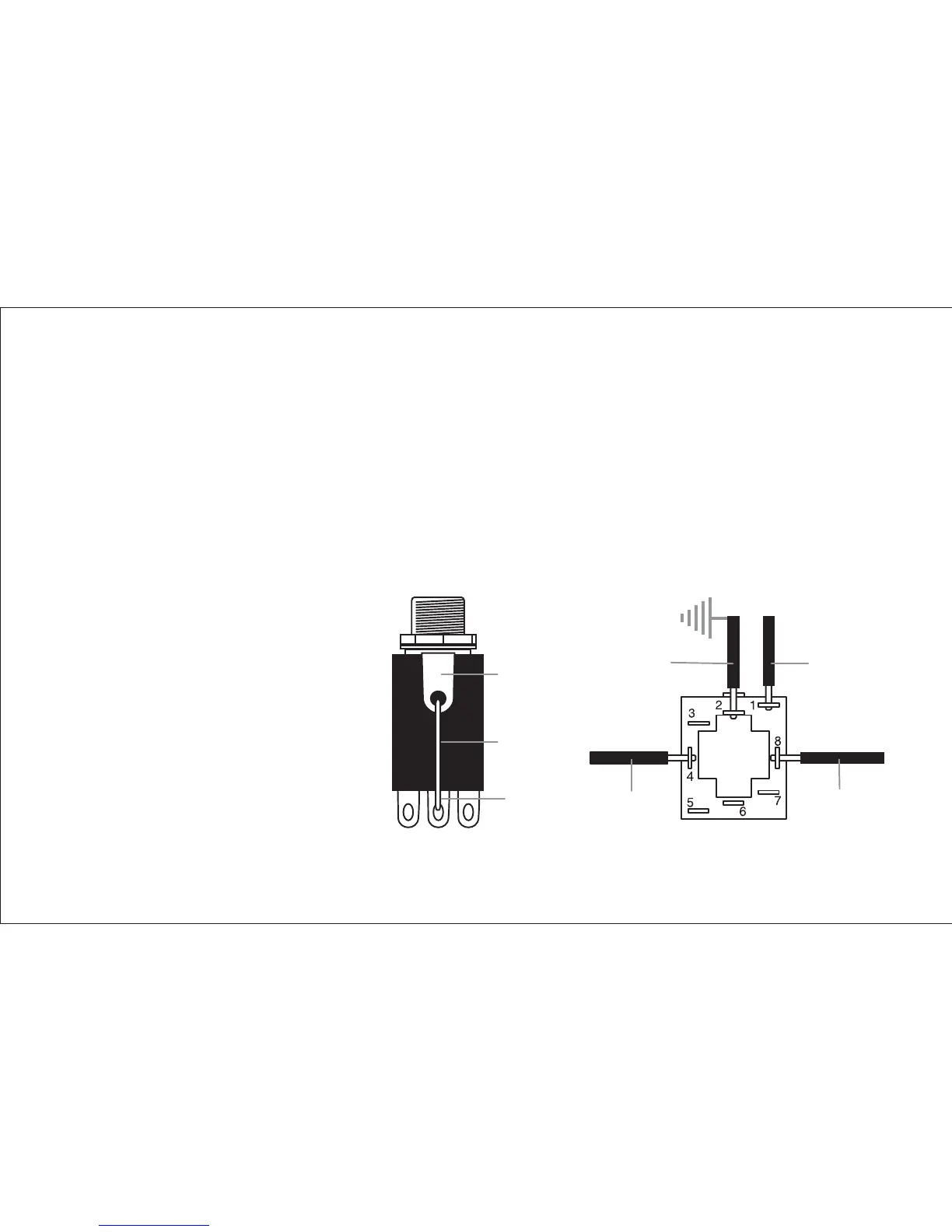
4. Solder the 9-pin jack to the system.
A prewired output cable from the Powerchip is to be soldered to the provided
9-pin jack. Prepare the jack by soldering a jumper wire between the sleeve
terminal, located on the business end of the jack, and terminal #2, directly below.
Solder the jack as follows:
a. Solder the shield from the output cable to terminal #2.
b. Solder the red wire from the output cable to terminal #4.
c. Solder the white wire
from the output cable
the terminal #8.
d. Solder the black
battery wire (negative)
to terminal #1.
Black
Battery
Wire
White Output
Wire (Ring)
Red Output
Wire (Tip)
Sleeve
Jumper
Wire
Terminal
#2
Output Ground
(Sleeve)