55FläktGroup DC_9355GB 20180119_R0 We reserve the right to make changes without prior notice
Alarm guide
Continued on next page
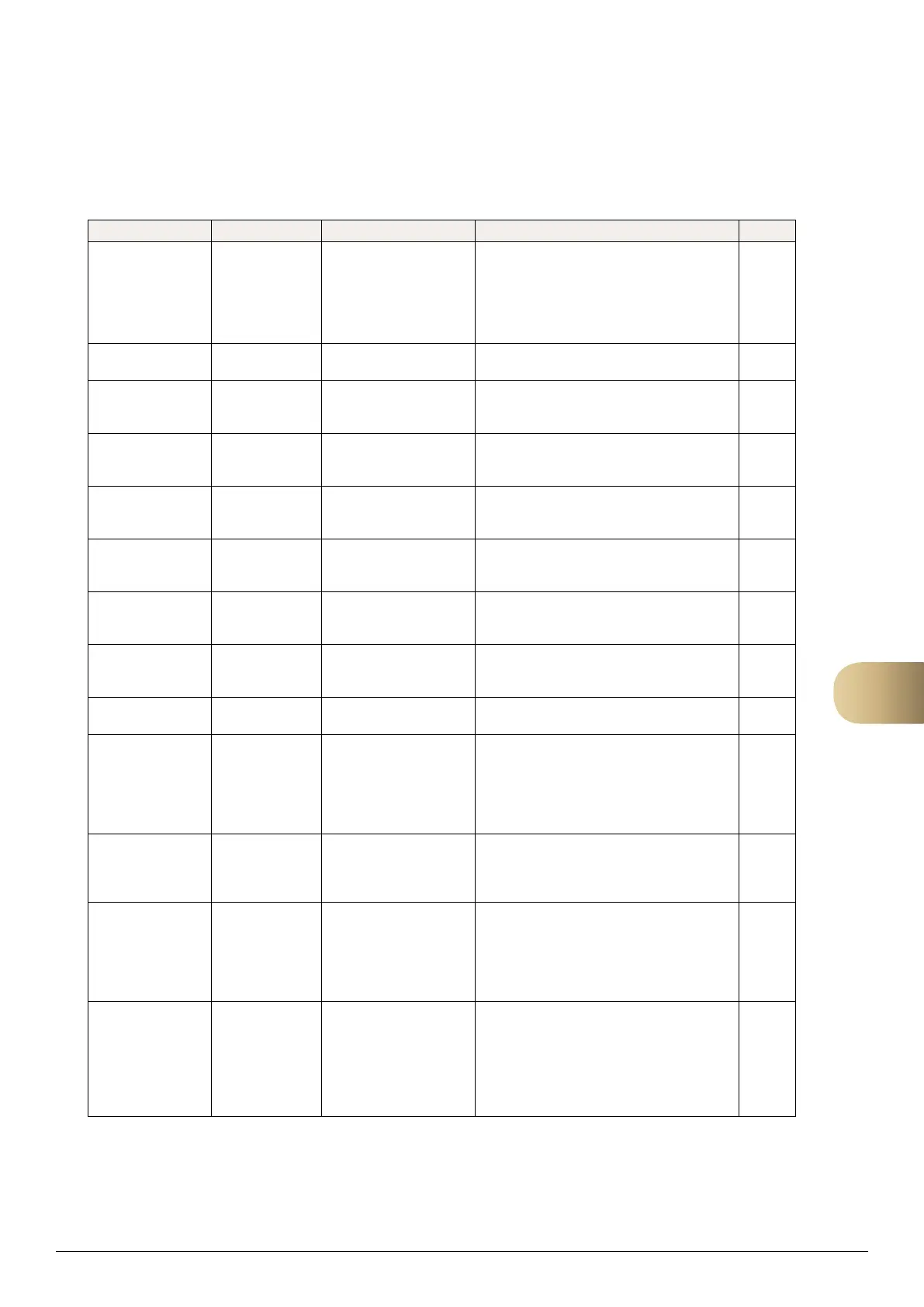
Alarms Alarm text Cause Action Type
Alarm electric heater El htg alarm:
Alarm
Terminal blocks 67-68 in
control cabinet indicate
alarm, normally caused by
thermal overload protection
in the electric heater.
• Check thermal overload protection
in electric heater.
• Check contact function for digital
input 2, compare with function
obtained from electric heater.
A
Alarm recovery unit Heat recovery
alarm: Alarm
• See other alarm points from the recovery
unit for further details.
B
Low voltage to rotor
operation
Hrec. Unit Volt low:
Alarm
The incoming supply
voltage is too low for rotor
operation.
• Check the supply voltage.
C
High voltage to rotor
operation
Hrec. Unit Volt
high:
Alarm
The incoming supply
voltage is too high for rotor
operation.
• Check the supply voltage.
C
Broken rotor belt Hrec. Unit
Brokenbelt:
Alarm
The drive belt on the rotor
has become detached or
loose.
• Check that the drive belt has not
become detached or loose.
C
Rotor motor
locked/blocked
Hrec. Unit Motor
blocked:
Alarm
The rotor moves too slowly
or is jammed.
• Check that the rotor is not moving more
slowly than usual and is not jammed.
C
Faulty sensor on
rotor motor
Hrec. Unit Sensor
error:
Alarm
Faulty sensor in rotor motor. • Contact FläktGroup support. C
High temperature in
rotor motor
Hrec. Unit High
temp:
Alarm
Motor has been running hot. • Check that the rotor is not moving more
slowly than usual and is not jammed.
C
DIP switch error in
rotor operation
Hrec Unit DIP error:
Alarm
DIP switch has
unauthorised setting.
• Reset to factory setting.
C
Cooling pump alarm Cooling pump
alarm: Alarm
Terminal blocks 61-62 in
control cabinet indicate
alarm, normally caused
by motor protection in the
chilled water circulation
pump.
• Check motor protection in chilled water
circulation pump.
• Check contact function for digital input 1,
compare with function obtained from pump.
B
Alarm DX cooling Cooling DX
alarm
Terminal blocks 61-62 in
control cabinet indicate
alarm, normally caused by
alarm from condenser.
• Check alarm from condenser.
• Check contact function for digital input 1,
compare with function obtained from
condenser.
B
Alarm supply air filter Supply filter alarm The measured differential
pressure over the supply
air filter exceeds the set
alarm level, normally due
to soiling.
• Check the supply air filter and replace if
necessary.
• If the pressure drop over the supply air filter
is too high or too low in relation to the desired
final pressure drop. Adjust the alarm level
using the handheld terminal.
B
Alarm, extract air
filter
Exhaust Filter
alarm
The measured differential
pressure over the extract
air filter exceeds the set
alarm level, normally due
to soiling.
• Check the extract air filter and replace if
necessary.
• If the pressure drop over the extract air
filter is too high or too low in relation to
the desired final pressure drop.
Adjust the alarm level using the handheld
terminal.
B
14


 To Next Page