PowerFLARM Core Manual v.150 International
Connections
Overview
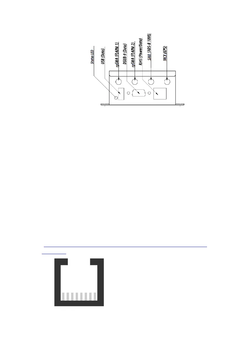
Core has the following connectors:
• USB 2.0: Flight log readout, device update and configuration
• FLARM antennas A and B: When using a single antenna, connect
to FLARM A. Antenna connector has a RED marking. Use of
FLARM B requires a feature license.
• ADS-B/PCAS: For receiving transponder signals. Antenna con-
nector has a BLUE marking.
• GPS antenna: Must be connected for proper operation in flight.
• Data Ports #1 (RJ45) and #2 (D-Sub DE9): For connecting up to
two independent displays/PDAs/flight computer. Also used for
power supply of Core. RX/TX on ports #1 and #2 can be config-
ured and used independently.
RJ45: Power and Data Connections
The 8-pin RJ45-socket is in accordance with IGC GNSS FR specifica-
tions, except for pin 3. Pin numbering follows IGC’s convention
(
http://www.fai.org/gnss-recording-devices/igc-approved-flight-
recorders ):
1: +12 to +28VDC power supply
2: +12 to +28VDC power supply
3: Core supplies +3VDC for display
4: GND
5: TX, Core sends (RS232)
6: RX, Core receives (RS232)
7: GND
8: GND
Pin 1 Pin 8