PowerFLARM Core Manual v.150 International
Maximum current on pin 8: 700mA @ 5VDC; shared with the USB
port.
Avoid using the 5VDC supply from the USB port and the D-Sub port
at the same time.
WARNING!
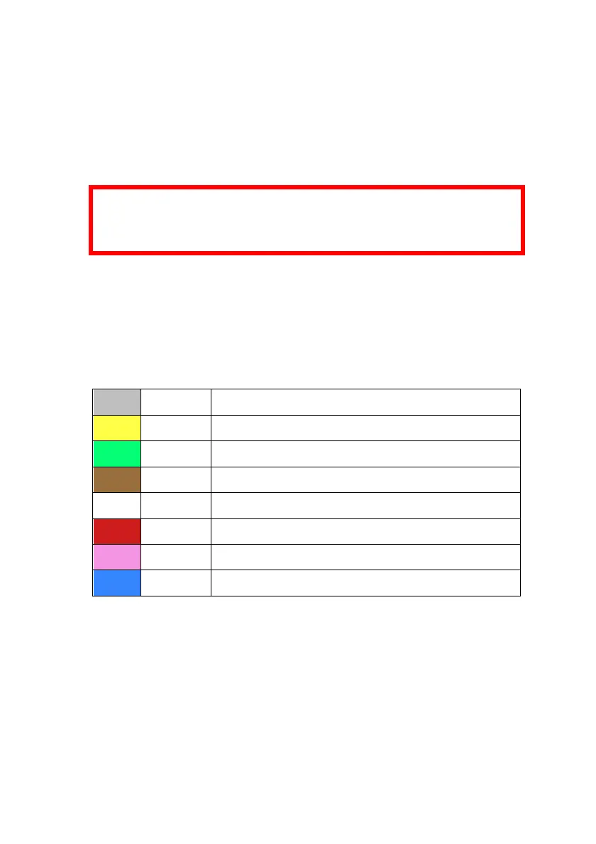
The below color assignments are only valid for specific D-Sub
cables which have been shipped with devices from 2016.
D-Sub cables shipped with PowerFLARM Core devices from 2016
are color coded according to the following table. These D-Sub cables
are marked with “Art.-Nr 1420531”. DO NOT use the color coding
if the cable is not marked accordingly.
Pin 2: TX, Core sends (RS232)
Pin 3: RX, Core receives (RS232)
Pin 7: +12 to +28VDC power supply
Pin 8: Core supplies +5VDC for PDA
Pin 9: Core supplies +3VDC for display
Note: There is no wire for Pin 6!
Pin 7 of the D-Sub connector and Pins 1 and 2 of the RJ45 con-
nector are internally connected. So are the GND pins 5 (D-Sub)
and 4, 7, 8 (RJ45).