The document describes the External FLARM™ / PowerFLARM™ Display V3+Mm for Powered Aircraft, a non-essential "situation awareness only" device designed to assist pilots by providing visual and acoustic warnings of nearby aircraft and fixed obstacles. It functions as a step-by-step display unit and operator control module for FLARM™ systems, with functions and operations generally identical to the original FLARM device.
Function Description
The V3+M display unit is designed to detect and alert the presence of other moving aircraft equipped with FLARM-compatible systems, ADS-B-OUT (1090ES) on 1090MHz, or interrogated transponders (Mode C or S). It does not have its own FLARM™ functions and cannot replace the main FLARM device. The display processes data received from the main FLARM unit and presents it to the pilot through a combination of LEDs, a two-digit distance display, and an acoustic buzzer.
The device operates in two main modes: "Nearest-Mode" and "Warning-Mode".
- Nearest-Mode: In this mode, the display indicates other aircraft in the nearby surroundings that do not represent an immediate threat after evaluation. This information is limited to a diameter of 3 km and a vertical separation of 500 m. The nearest aircraft is always indicated visually in yellow and statically (without flashing), without an acoustic sound. A clicking sound begins when an aircraft is received. If the FLARM system identifies an aircraft as a threat, the display automatically switches to "Warning-Mode."
- Warning-Mode: This mode is activated when the FLARM system confirms an approaching threat. Warnings are always shown with red flashing LEDs and are accompanied by an acoustic signal. The flashing and buzzing frequencies change based on three threat levels: moderate, severe, and immediate.
The display provides both horizontal and vertical bearings to other aircraft:
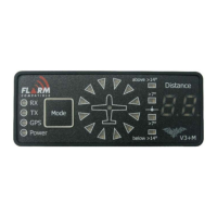
- Horizontal Bearings: Twelve 2-colour LEDs illustrate the compass rose, with "Above" conforming to the actual flight direction. Each LED represents a 30° horizontal section. Depending on the threat level (moderate, severe, immediate), 1, 2, or 3 LEDs may flash. The V3+M display can be configured to show warnings analogous to the FLARM™ indicators.
- Moderate threat: (approx. 19–25 seconds until possible collision) indicated by red LED and slow buzzer interval (~2 Hz).
- Severe threat: (approx. 14–18 seconds until possible collision) indicated by red LED and middle buzzer interval (~4 Hz).
- Immediate threat: (approx. 6–8 seconds until possible collision) indicated by red LED and rapid buzzer interval (~6 Hz).
- Vertical Bearings: These operate relative to the aircraft's own flight altitude and are indicated by four vertical LEDs. The indication is based on vertical bearing angle, not absolute altitude difference:
- No LED illuminated: vertical bearing angle less than 7°.
- Inner LEDs illuminated: vertical bearing angle of 7° to 14°.
- Outer LEDs illuminated: vertical bearing angle more than 14°.
The flashing frequency is synchronous with the horizontal indicators.
The device also features Transponder Object Indication:
- For transponders with ADS-B-OUT, the FLARM™ system can evaluate GPS-coordinates, calculate collision threats, and provide warnings identical to "Airplane Warning."
- For transponders without ADS-B-OUT (Mode C/S), FLARM™ cannot calculate distance and direction but can determine proximity based on signal strength, providing a distance indication.
Fixed-Obstacle Warning: Many FLARM™ systems include a fixed-obstacles database. If the main FLARM device has this database, the V3+M display can illustrate appropriate traffic information and warnings. When a collision threat with a fixed obstacle is calculated, the system warns with simultaneous flashing of two LEDs, and the flashing and buzzing rate depends on the threat (similar to "Aircraft Warning"). Fixed-obstacle warnings do not provide specific direction or vertical position indications.
An Indicator Mute-mode can be activated by a double-click of the "Mode" button, suppressing all visual and acoustic traffic, fixed-obstacle, and threat information for 5 minutes. This is confirmed by a decreasing sound sequence and automatically cancels after 5 minutes with an increasing sound sequence.
Important Technical Specifications
- Dimensions: 25 x 63 x 5.6 mm (excluding RJ12-jack, which adds approximately 10 mm backwards).
- Weight: 11.6 g (display without cable and adapter).
- Supply voltage: VCC DC directly from FLARM, with an allowed input voltage range from 8 to 35V DC. The display has its own voltage stabilizer.
- Power consumption: Average 12 mA by 12V (144 mW).
- Protection class: IP52.
- Attachment: Panel attachment (adhesion or screw).
- Temperature range: -20°C to 60°C.
- Humidity: 10-90%, no condensation.
- Vibrations: Suitable for applications in strong vibrating conditions (e.g., helicopter, powered aircraft).
- Manufacturing country: Switzerland.
Pin Allocation Display (6-pole RJ12-jack):
- 8-35 VDC (battery supply from FLARM)
- Not connected (3.3V from FLARM)
- RS232-GND (internally connected to pin 6)
- RS232-RX: display receives data from FLARM
- RS232-TX: display sends data to FLARM
- GND (internally connected to pin 3)
Usage Features
- Operator Control: All functions are operated using a single "Mode" button, designed for tactile feedback and operation with gloves.
- Status Indicators: Four vertically situated green status-LEDs indicate the operating status of the FLARM™ system:
- RX (Receive): Flashes upon reception of other devices in range; otherwise, off.
- TX (Transmit): Flashes during operation when own signals/positions are sent (requires correct GPS-reception).
- GPS: Flashes constantly during operation (interruption once/sec). If off or flashing once/sec, no GPS-reception exists.
- Power: Illuminated constantly during operation. Blinks if voltage is below 8 VDC.
- Distance Indicator: A two-digit red display shows distance from 0.1 to 99. Values > 9.9 may occur with ADSB transponder receivers. Configurable in KM (kilometers) or NM (nautical miles), indicated briefly on startup.
- Brightness Sensor: Centered in the airplane symbol, it ensures adequate readability in varying light conditions, including direct sunlight. Brightness can be fixed or automatically adjusted.
- Acoustic Signal (Buzzer): Located on the lower edge of the display, it provides acoustic warnings in addition to red indicators during approaching threats. Volume can be adjusted to 4 levels (loud, medium, silent, mute). Default is "loud" for safety.
- Configuration Mode: Accessed by disconnecting and reconnecting power while holding the "Mode" button. Allows adjustment of parameters such as brightness, parallel operation settings (PIC/PAX), FLARM™ mainframe operation (e.g., switching off mainframe buzzer), interface transmission rate (baud rate), distance unit (KM/NM), and compatibility mode (LED indication style).
- Parallel Operation: Two external displays can be operated on FLARM™ or PowerFLARM™ using a Y-adapter. One display must be configured as "PAX" to avoid data collisions.
- Start-up Sequence: Upon power-on, the display performs a self-test, shows its software version, conducts an LED-test (in groups), briefly displays the configured measuring unit, and then is ready for use. The Power LED flashes and GPS LED blinks until the system defines its position.
Maintenance Features
- Maintenance-Free Display: The V3+M display itself is maintenance-free.
- Recommended Checks:
- Verify all LEDs illuminate during the start-up test.
- Check "Mode" button function; ensure no dirt/dust obstructs it.
- Ensure buzzer opening is free from dirt or adhesive residues.
- Confirm all 4 volume levels are audible.
- For the FLARM™ mainframe: check software and fixed-obstacle database currency, antenna integrity, and cable/plug condition.
- Software Updates: The V3+M display is equipped with a boot-loader, allowing updates to its integrated software. Updates are provided by FLARM™ for changes/additions to data communication or adjustments to warning levels. Updates are typically compatible with current peripheral devices and can introduce new functions. Information and update steps are available on www.flarm.com/support/updates/ and www.swiss-bat.ch.
- Adhesive Attachment: Two pre-cut double-sided mounting adhesives are included. Surfaces must be clean and oil-free for optimal adhesion. To remove, use a knife to cut under the display to avoid damaging electronics.
- Screw Attachment: Two M2 screw holes are provided for alternative attachment. Screws must not penetrate more than 3 mm into the display. Non-magnetic brass screws are recommended to reduce interference with compasses.