Manual external FLARM™ / PowerFLARM™ Display V3+Mm
External FLARM™/ PowrFLARM™ Display
V3+Mm
with Software-version 3.7
Page 7
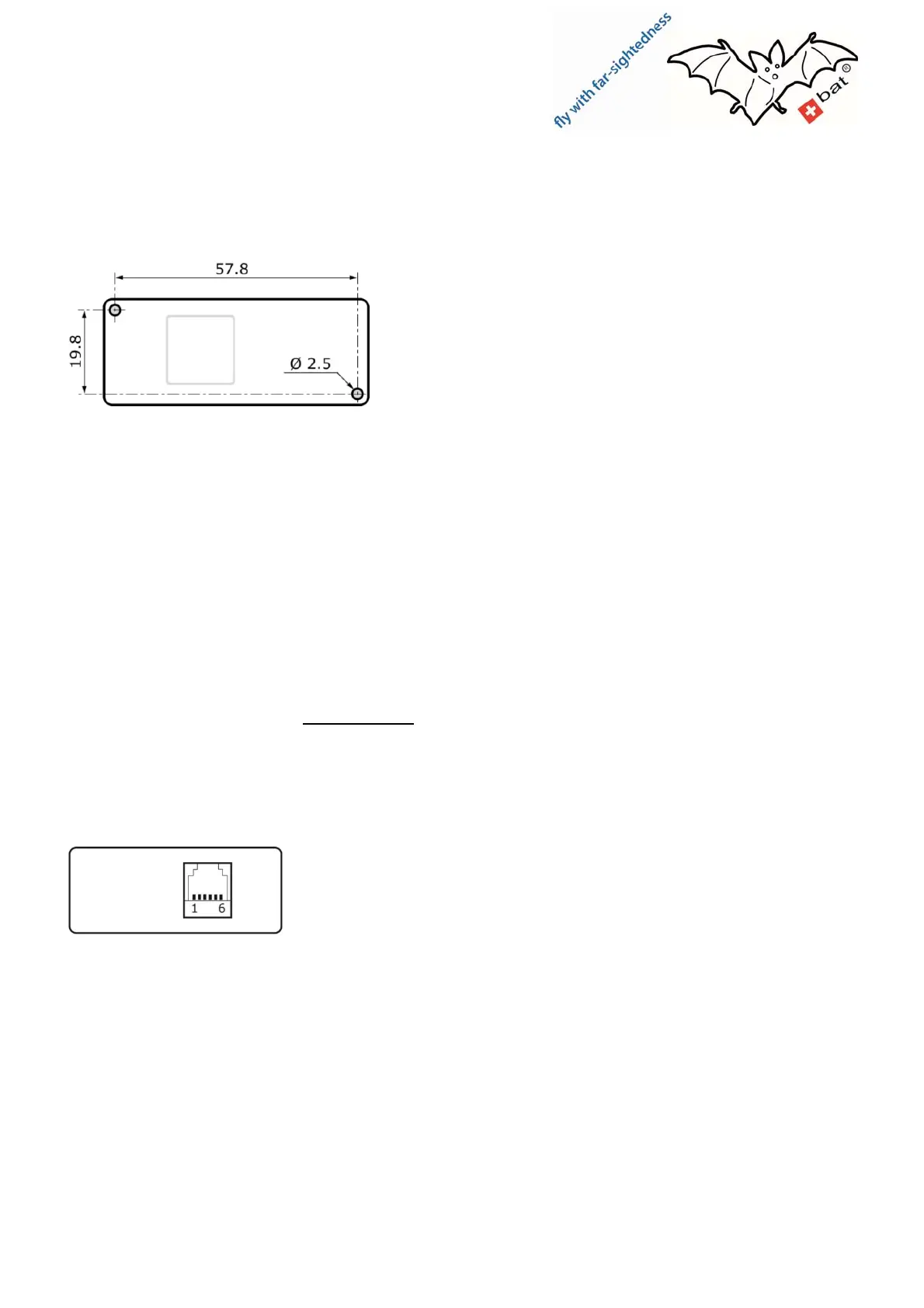
Screw Attachment
When the adhesive method proves unsuitable, attaching the unit with screws is possible; for this purpose
there are two M2 screw holes present in unit.
screw fastening (front view)
Attention:
The M2 screws must not enter further than 3 mm
into the display – shorten screws if necessary!
Important: when the screws penetrate too far into the casing, damage to the electronics of the display can
occur. It is mandatory to measure the length of the screws beforehand!
Tip: influences on the compass, other magnetic-influenced instruments and sensors can be reduced by using
(non-magnetic) brass screws.
Power supply
There are power sockets on the display that connect to the mainframe. In addition to data communication the
FLARM
TM
instruments have a “non-stabilized” battery supply available on their interface. This enables the
peripheral device’s power supply through simple wiring.
Non-stabilized means the FLARM-device supply is connected without voltage control and without internal
fuse protection to the interface. Strictly adhere to the manufacturer’s references regarding the connection
and fuse protection of the mainframe.
The display V3+M has its own voltage stabilizer for its electronics – with an allowed input voltage range from
8 to 35V DC – and was developed for the nominal (battery) supply of 8 … 35V.
Pin allocation display
Display rear view
1: 8-35 VDC (battery supply from FLARM)
2: not connected (3.3V from FLARM)
3: RS232-GND, internally connected to pin 6
4: RS232-RX: display receives data from FLARM
5: RS232-TX: display sends data to FLARM
6: GND, internally connected to pin 3
The 6-core connecting cable provided and optional Y-adapter are wired 1:1. (Pin 1 of plug 1 goes to pin 1 of
plug 2 etc.)
Any warranty legal claim through improper installation/wiring will be explicitly declined.