21
Urządzenie wyposarzone jest w następu-
jące złącza:
1. DMX (we/wy): gniazdo XLR 3-pin
2. EHTERNET (we/wy): gniazdo RJ-45
2. Zasilanie (we/wy): gniazdo powerCON
TRUE1
1
3
2 2
SHIELD
SIGNAL (+)
SIGNAL (-)
3
1
FEMALE
MALE
XLR
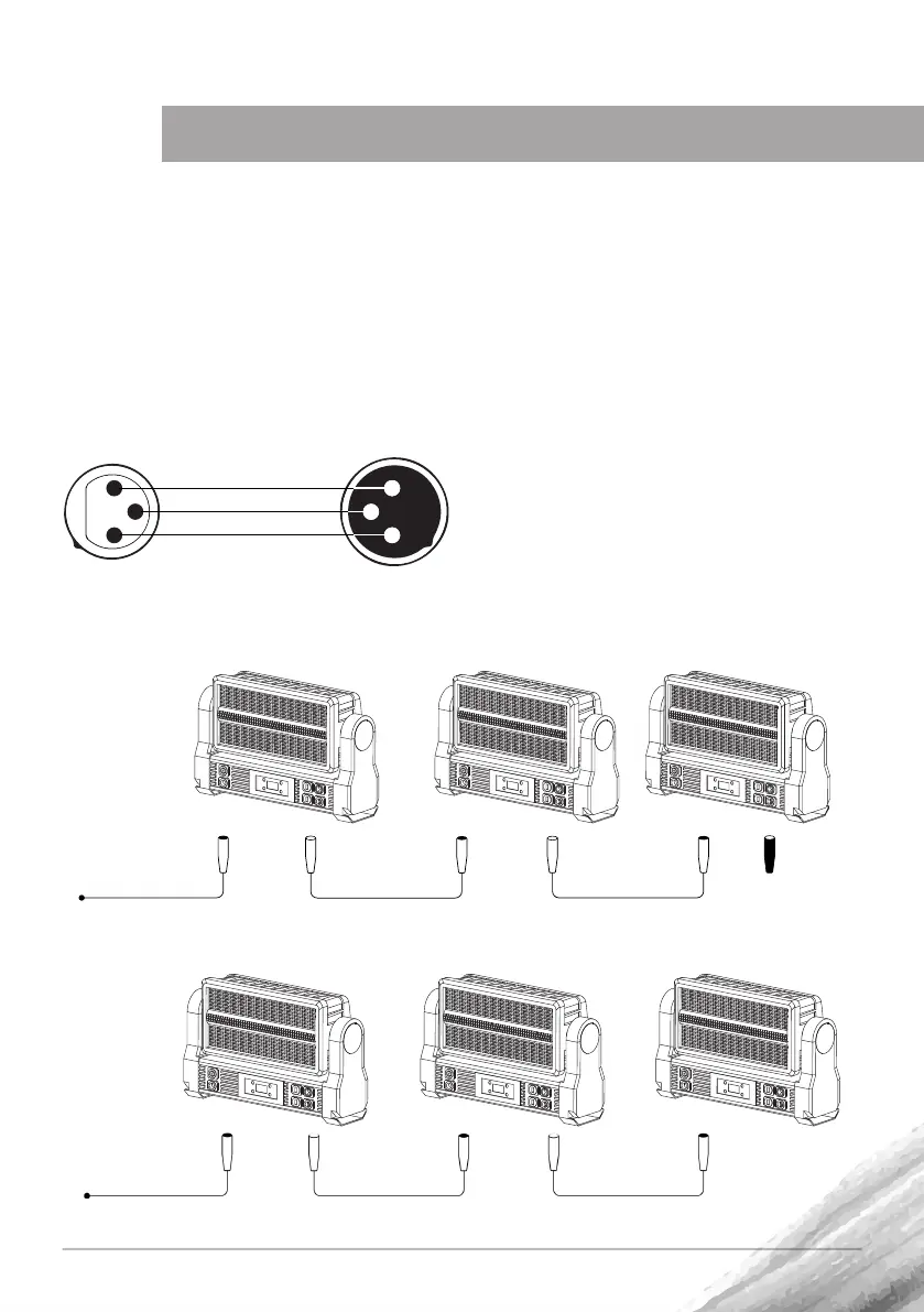
UWAGA! Ostatnie urządzenie w łań-
cuchu połączenia DMX powinno być
zakończone terminatorem. Rezystor
120Ω zalutowany powinien być między
sygnałem (-) a sygnałem (+) w złączu
XLR.
3-PIN XLR
Połączenie sygnału odbywa się za pośred-
nictwem przewodów:
DMX (XLR-żeński -> XLR męski)
lub
ETHERNET (RJ-45)
PODŁĄCZENIE
Schemat połączenia szeregowego urządzeń przewodem DMX
Dystrybutor
ArtNet
RJ-45 RJ-45
Schemat połączenia urządzeń za pomocą przewodu RJ-45 (ethernet)
DMX
Controller
DMX 512 DMX 512 120
 Loading...