optional 12-volt refrigerator may also have a fuse
in
the
line supplying power
to
the appliance. Fuses for the
motor home chassis circuit are located on a panel under
the dash behind
the
steering column. See
your
Chassis
Operator's Manual for further information.
Optional
eq-
uipment may have additional fuses installed: refer
to
the
equipment instructions for information.
NOTE:
If
fuse replacement
is
necessary, replace with
fuses
of
the
same amperage.
AUXILIARY 12-VOLT BATTERY
The
motor
home
is
equipped with an auxiliary 12-volt
battery. It will be installed
in
the
location shown
in
Fig-
ure 4.
The
auxiliary battery
is
the
primary source for
. normal living-area power needs. Sensing .and switching
circuits permit
the
vehicle alternator
to
charge
both
bat-
teries as required and prevent
the
living area 12-volt
re-
I~_:;:;::::iiii
quirements from depleting
the
vehicle battery.
If
the
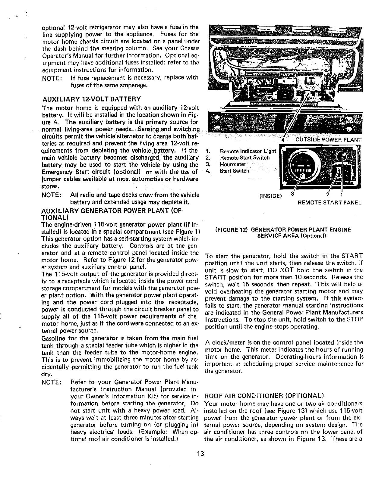
1.
Remote
Indicator
Light
main vehicle
battery
becomes discharged,
the
auxiliary 2.
Remote
Start
Switch
battery
may
be used
to
start
the
vehicle
by
using
the
3.
Hourmeter
Emergency
Start
circuit (optional)
or
with
the
use
of
4.
Start
Switch
jumper cables available
at
most automotive
or
hardware
stores.
NOTE: All radio and
tape
decks draw from
the
vehicle
battery
and extended usage may deplete it.
AUXILIARY GENERATOR POWER PLANT (OP-
TIONAL)
The engine-driven 115-volt generator power plant (if
in-
stalled)
is
located
in
a special compartment (see Figure
1)
This generator
option
has a self-starting system which
in-
cludes
the
auxiliary battery. Controls are
at
the
gen-
erator and
at
a remote control panel located inside
the
motor home. Refer
to
Figure 12 for
the
generator pow-
er system and auxiliary
contwl
panel.
The 115-volt
output
of
the generator
is
provided direct-
ly
to
a receptacle which
is
located inside
the
power cord
storage
compartment
for models with
the
generator pow-
er
plant
option. With
the
generator power
plant
operat-
ing and
the
power cord plugged into this receptacle,
power
is
conducted through the circuit breaker panel
to
supply all
of
the
115-volt power requirements
of
the
motor
home, just as if
the
cord were connected
to
an ex-
ternal power source.
Gasoline for
the
generator
is
taken from
the
main fuel
tank through a special feeder
tube
which
is
higher
in
the
tank
than
the feeder
tube
to
the
motor-home engine.
This
is
to
prevent immobilizing
the
motor home by
ac-
cidentally permitting
the
generator
to
run
the
fuel tank
dry.
NOTE: Refer
to
your
Generator Power Plant
Manu-
facturer's I nstruction Manual (provided
in
your
Owner's I nformation
Kit)
for service
in-
formation before starting
the
generator,
Do
not
start
unit
with a heavy power load.
Al-
ways wait
at
least three minutes
after
starting
generator before turning on (or plugging
in)
heavy electrical loads. (Example: When op-
tional roof air conditioner
is
installed.)
13
(INSIDE)
REMOTE
START
PANEL
(FIGURE
12)
GENERATOR
POWER
PLANT
ENGINE
SERVICE
AREA
(Optiona\)
To
start
the
generator, hold
the
switch in
the
START
position until
the
unit starts,
then
release
the
switch.
If
unit
is
slow
to
start,
DO
NOT hold
the
switch
in
the
START position for more
than
10 seconds. Release the
switch, wait 15 seconds,
then
repeat.
This
will help
a-
void overheating
the
generator starting
motor
and may
prevent damage
to
the
starting system.
If
this system
fails
to
start,
the
generator manual starting instructions
are indicated.
in
the
General Power
Plant
Manufacturers
Instructions.
To
stop
the
unit, hold switch
to
the
STOP
position until
the
engine stops operating.
A clock/meter
is
on
the
control panel located inside the
motor
home. This meter indicates
the
hours
of
running
time on the generator. Operating-hours information
is
important
in
scheduling proper service maintenance for
the
generator.
ROOF AIR CONDITIONER (OPTIONAL)
Your motor home may have one
or
two
air conditioners
installed on the roof (see Figure 13) which use 115-volt
power from
the
generator power plant
or
from
the
ex-
ternal power source, depending
on
syStem design. The
air conditioner has three controls
on
the
lower panel
of
the
air conditioner,
as
shown
in
Fi~ure
13. These are a
 Loading...
