GE 5/GE 5 R/GSE 5/GSE 5 R
25
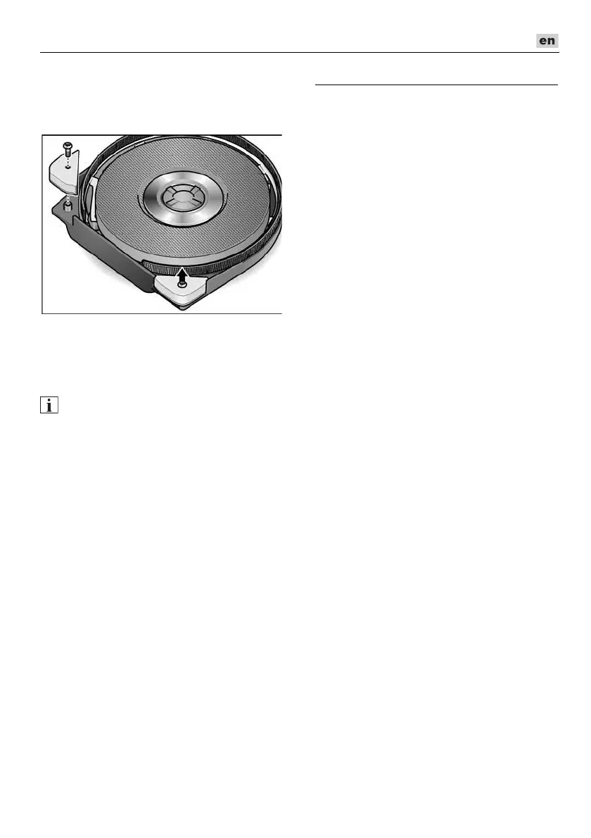
Replacing the protective corners
(GE 5 R/GSE 5 R)
Remove protective corners
to be replaced.
Attach new protective corners.
Repairs
Repairs may be carried out by an authorised
customer service centre only.
NOTE
During the warranty period do not loosen
the screws on the housing.
Non-compliance will deem the guarantee
obligations of the manufacturer null and
void.
Spare parts and accessories
Other accessories, in particular insertion
tools, can be found in the manufacturer’s
catalogues.
Exploded drawings and spare-part lists
can be found on our homepage:
www.flex-tools.com
Exemption from liability
The manufacturer and his representative
are not liable for any damage and lost profit
due to interruption in business caused
by the product or by an unusable product.
The manufacturer and his representative are
not liable for any damage which was caused
by improper use of the product or by use
of the product with products from other
manufacturers.