11
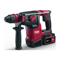
GPH 18-EC
Symbols used in this manual
WARNING!
Denotes impending danger. Non-observance
of this warning may result in death or
extremely severe injuries.
CAUTION!
Denotes a possibly dangerous situation. Non-
observance of this warning may result in
slight injury or damage to property.
NOTE
Denotes application tips and important
information.
Symbols on the power tool
V Volts
Read the instructions!
Disposal information for the old
machine
For your safety
WARNING!
Before using the power tool, please read the
follow:
these operating instructions,
the “General safety instructions” on the
handling of power tools in the enclosed
booklet (leaflet-no.: 315.915),
the currently valid site rules and the
regulations for the prevention of
accidents.
This power tool is state of the art and has
been constructed in accordance with the
acknowledged safety regulations.
Nevertheless, when in use, the power tool may
be a danger to life and limb of the user or a third
party, or the power tool or other property may be
damaged.
The power head may be used only
as intended,
in perfect working order.
Faults that impair safety must be repaired
immediately.
Intended use
The power head is intended
–
for commercial use in industry and trade,
–
for using with only the following FLEX
attachments Line Trimmer GLT 35 or
subsequently introduced by FLEX.
Technical data
Tool GPH 18-EC
Type Power Head
Voltage Vdc 18V
Weight
(without
battery back)
kg 2.7
Battery 18V
AP 18.0/2.5
AP 18.0/5.0
AP 18.0/8.0
Weight of
battery
kg
AP 18.0/2.5
AP 18.0/5.0
AP 18.0/8.0
0.4
0.7
1.1
Working
Temperature
-10~40°C
Charging
Temperature
4~40°C
Storage
Temperature
<50°C
Charger
CA 10.8/18.0,
CA 18.0-LD
Overview (see figure A)
The numbering of the product features refers
to the illustration of the machine on the
graphics page.
1. Wing knob
2. Coupler
3. Shoulder-strap loop
4. Speed mode switch
5. Lock-off button
6. Variable-speed trigger switch
7. Rear handle
8. Front-assist handle
9. Assist-handle lock-lever
10. Screw knob