13
2. Replace the cleaned/shaken bag filter in the container.
Make sure the filter support fits into the inner edge of the
dust container properly.
Check that the filter is fitted the right way up - the cloth
handle on the filter should be visible.
3. Replace the dust container on the vacuum unit. Close the
container on the vacuum unit by applying inward pressure
to the two handles to ensure the vacuum unit and dust
These products must though always be
operated with the bag filter fitted in the
cleaner
8 Electrical connecction
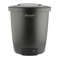
CVR 1000
The connection panel is
located in the bottom of
the vacuum unit
CVR 2000, CVR
3000, CVR 4000
The connection panel is
located in the top of the
vacuum unit
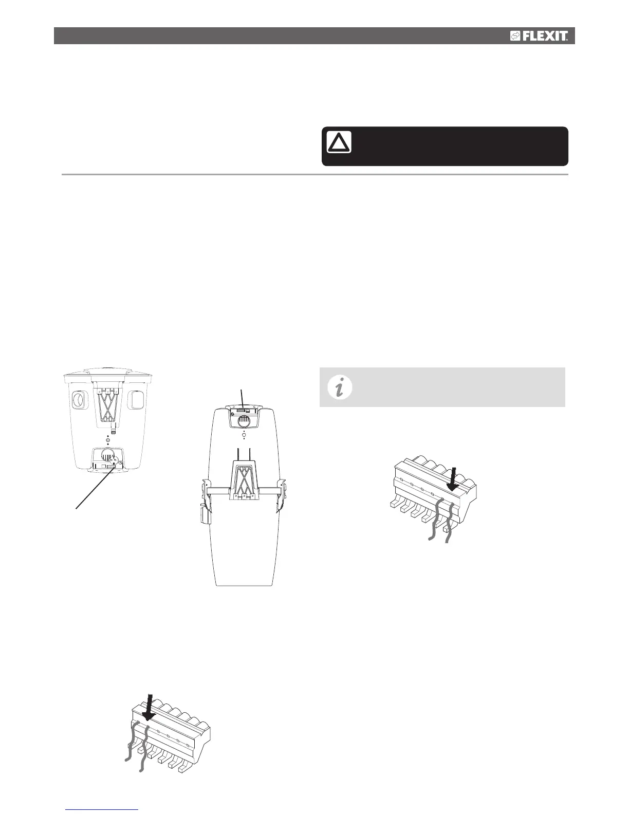
CVR 1000
Connection panel for low voltage lead
The low voltage leads are connected by snap lockings. Insert
leads in the snap lockings (one in each point). Secure the low
voltage cables by pulling the snap lockings at the connector
upwards.
Secure the low voltage
cables at the connector
Connect forcing
signal to this outlet.
Forcing signal ventilation unit
Connection to units capable of receiving pilot signal for
forcing of supply air.
When the vacuum cleaner starts, the ventilation unit
will increase the volume of air during vacuuming. This to
compensate for the air the vacuum cleaner draws out of
your house. When the vacuum cleaner is switched off, the
ventilation unit returns to original speed.
To be connected with a low voltage lead between the vacuum
cleaner and the ventilation unit.
Connection to ventilation unit; see
operating instructions of the unit
container are fitted together properly.
CVR 2000 / CVR 3000 / CVR 4000 can be run with or
without the installation of a dust bag - the choice is yours.
Connection of pilot current
The pilot current outlet (low voltage) is connected to a low
voltage lead running the length of the pipes. Both ends of
the low voltage lead are connected to the connection panel
on the vacuum unit. One lead to each outlet, see illustration
below.