© 2013 Flex Radio Systems. All rights reserved.
i. Connect the other end of the ATU control ribbon cable to connector labeled “P1” on the side of the ATU board
located towards the front of the FLEX-5000. The red strip (pin 1) on the cable is oriented towards the front of the
FLEX-5000. Do NOT connect the ATU control cable to the ICSP connector in the middle of the ATU board. (See
Figure 9)
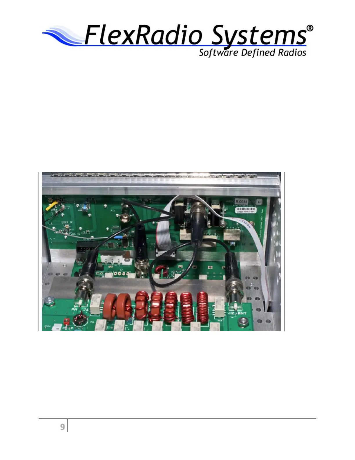
j. Locate the short mini coax cable connection between the BNC connector labeled “PA Out” on the PA board and
the BNC connector labeled “J4 PA/ATU” on the RFIO board mounted on the rear panel of the radio.
k. Remove the mini coax cable from the RFIO BNC connector referenced in step 14 and connect it to the BNC
connector on the ATU board labeled “PA J1”. (See Figure 11)
i. Connect one end of the supplied BNC mini coax cable to the BNC connector on the ATU labeled “J2 ANT” and the
other end to the BNC connector labeled “J4 PA/ATU” on the RFIO board mounted on the rear panel of the radio.
(See Figure 11)
Figure 11 - Routing of BNC cables between PA, ATU, and I/O panel
j. Confirm that your connections between the BNC connectors on the PA, ATU, and RFIO panel are routed as shown
in Figure 11.