FLEX-6400/FLEX-6600 Hardware Reference Manual
Page 23 of 45
Copyright 2018 FlexRadio Systems. All Rights Reserved.
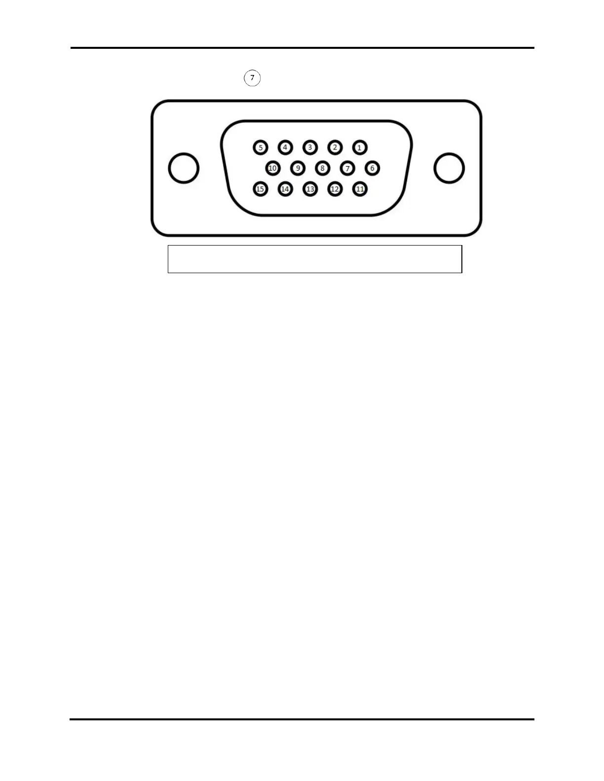
7.6 ACCESSORY CONNECTOR
The accessory connector is a high-density HD-15 female connector. There are a number
of inputs and outputs on this connector.
! - This is the same type of connector used by VGA monitors. Do not connect to VGA
monitors.
Δ – All Accessory inputs are 3.3VDC MAX Input
7.6.1 Pin 1: Line In
This audio line input can be used to feed consumer level (-10dBV) audio into the
transmitter. Refer to the SmartSDR documentation for information describing how to
enable this input, and what configurations are available.
7.6.2 Pin 2: Line1 Out
This audio line output is a buffered output of the POWERED SPEAKERS left channel.
7.6.3 Pin 3: Line2 Out
This audio line output is a buffered output of the POWERED SPEAKERS right channel.
7.6.4 Pin 4: KEY In
This input is a keying input for CW. Refer to the SmartSDR documentation for
information describing how to enable this input, and what configurations are available.
Pin 4 is keyed to GROUND.