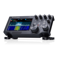
2.0 MAKING THE CONNECTIONS
The following steps describe the required connections for
getting your Maestro connected to your FLEX-6000 Signature
Series SDR.
First Steps:
1. Carefully remove the packaged accessories and the
Maestro from the shipping carton and identify all of the
supplied accessories listed in the previous section.
2. Attach the included xed angle foot, or the optional tilt
feet if ordered, to the back of the unit using the provided
screws.
3. Place the Maestro in your operating position making sure
it has adequate ventilation.
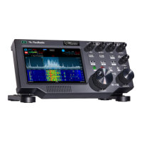
Back Panel Connections
1.) Ethernet - If you plan to connect your Maestro to your FLEX-
6000 Signature Series radio via a wired connection, plug one
end of the supplied Ethernet cable into the Ethernet socket on
the Maestro side panel. Connect the other end of the cable
to the FLEX-6000 Series radio, either directly or via a local
area network (LAN). When connected via a LAN, it should
be plugged into an available 100/1000 BASE-T Ethernet port
on your rewall/router or to an Ethernet switch on the same IP
subnet as your FLEX-6000 Signature series radio.
Additional Required and Optional Items Not Supplied with
the Maestro Console:
In addition to the accessories, parts and cables supplied with
the Maestro unit, you must provide the following:
One of the following connections to your FLEX-6000 Signature
Series radio:
1. A wired Ethernet connection on your local area network
(LAN) allowing a connection to ports on your radio, or
2. A WiFi connection to the network on which your radio is
connected, or
3. A network connection from the Maestro to your radio (WiFi
or Ethernet), and a
4. AC or DC power source
And you may optionally choose to provide one or more of the
following:
1. Powered stereo speakers (computer type) and/or stereo
headphones
2. A microphone and headphone combo with a TRRS CTIA-
wired connector inserted in the HDST Combo Mic and
Headphone Connector
3. A straight key, paddles or a keyer with a 1/8" TRS plug
4. A rechargeable battery pack to power the unit without the
use of the 24-volt DC power supply.
5. Separate PTT switch
6. External Monitor connected via external display cable.
2.0 MAKING THE CONNECTIONS
 Loading...