Connector Pin # Intercom Function Aircraft Connection
1 Ground Avionics ground point
2 Mic Audio Pilot
3 Mic Audio Co-pilot
4 Mic Audio Navigator or Passenger #1
5 Navigator Key Navigator PTT switch
6 Co-pilot Key Co-pilot PTT switch
7 Pilot Key Pilot PTT switch
8 Xmit Key Com radio keyline
9 ICS Audio A Pilot headphone
10 ICS Audio B Pilot headphone
11 ICS Audio A Passenger headphones
12 ICS Audio B Passenger headphones
13 Mic Return All mic jacks
14 Mic Audio Passenger #2
15 Mic Audio Passenger #3
16 Mic Audio Passenger #4
17 Xmit Audio Com radio
18 Aux Input A Music system
19 Aux Input B Music system
20 Power In 12 to 28 volts, 1 amp breaker
21 Recv Audio NavCom or Audio panel
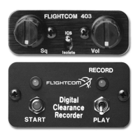
22 DCR Power DCR indicators
23 Active LED Amber LED
24 Start Start button
25 Record Play/Record switch (Red LED)
Wiring Suggestions
To wire the 403 and 403d intercoms:
1. Using a 25 watt soldering iron and 20 or 22 gauge Teflon-coated wire, make solder connections that are
insulated with heat shrink tubing (page 6, Figure 8) and (page 4, Figure 6) for connector pin numbers and
connection information.
2. Carefully route all wires away from aircraft controls, so that wires do not chafe on or come in contact with
control cables, push rods, trim actuators, chains, flap followers, or other moving devices, and:
• Avoid bundling wires with an RF inverter, coaxial cables, or synchro wiring.
• Use shielded wire for microphone, headphone, and audio wiring.
• Connect the intercom power lead (pin 20) to a circuit breaker on the Avionics Power Bus, not to the
Flight Instrument Power.
• Avoid circuits with motors, strobes, or other “noisy” devices.
NOTE: numbers are located on the solder terminal side of the 25-pin D-sub connectors.
If you are not sure where to obtain power, consult with an avionics shop before continuing.
Wire Connection Code
The connector pin numbers indicated in the following table correspond to the numbers on the D-sub connector
included with the 403 and 403d intercoms.
The stereo connection schematic includes a third person radio transmit connection. Delete the connection
to pin number 5 when only installing a two-place radio transmit system, which is the most common
pilot/co-pilot configuration (page 4, Figure 6).
7
 Loading...