P
N
P
A
ss
e
mb
ly
I
nstructions
S
-
EN
h
r
�
Antenna
h
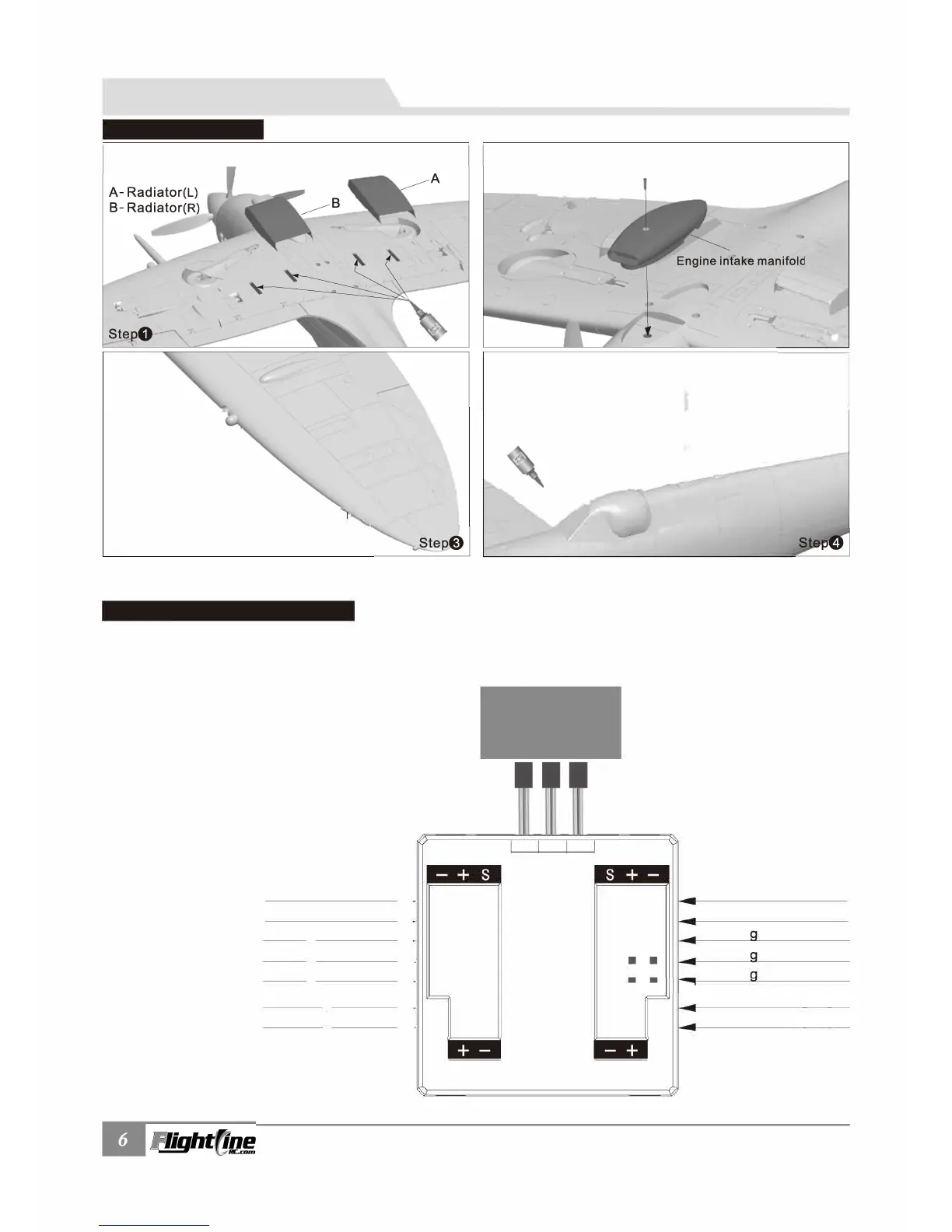
Using the diagram as a guide, insert the landing gear,
LED lights and flaps into the designated input plug.
Then plug the Flap, L-G and Ail output plugs into the
receiver. Rudder and elevator servos will plug directly
into the receiver.
Control board functions:
1. Replaces Y-cables and other connection cables,
allowing for a cleaner wiring job and better quality
connections.
2. The board is an all-in-one control surface/LED
light control board.
RECEIVER
AIL
G-D
G-D
G-D
Light Light
Light Light
0
PITFIRE MK.IXc
lten No.: FLW303
2.Use 1xPWM4x8mm screw to attach the air intake.
Note: After completing the above steps, depending on the model of your control board, insert the
aileron, flap and landing gear cables to the control board
.