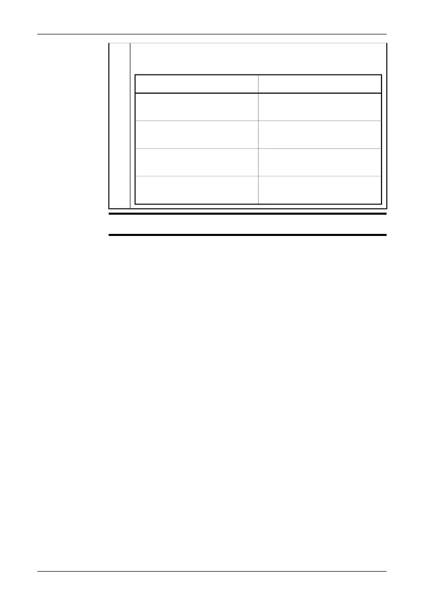
EasyManuals Logo

FLIR A3 series Installation Manual

FLIR A3 series
108 pages
To Next Page IconTo Next Page
To Previous Page IconTo Previous Page
Page #31 background imageLoading...
Page #31 background image
Power indicator
Note: The LEDs indicate the following:
ExplanationType of signal
The camera is starting up.The LED glows continuously or-
ange.
An error has been detected. Con-
tact service.
The LED glows continuously red.
The camera has started.The LED glows continuously
green.
An error has been detected. Con-
tact service.
The LED flashes 10 times per sec-
ond.
B
NOTE
Cables for digital I/O ports should be 100 m/328 ft. maximum.
Publ. No. T559498 Rev. a461 ENGLISH (EN) August 19, 2010 25
10 Connectors, controls, and indicators

Table of Contents

Other manuals for FLIR A3 series

Questions and Answers:

Question and Answer IconNeed help?

Do you have a question about the FLIR A3 series and is the answer not in the manual?

FLIR A3 series Specifications

General IconGeneral
BrandFLIR
ModelA3 series
CategoryThermographic Cameras
LanguageEnglish

Related product manuals