10 Connectors, controls, and
indicators
FLIR A3XX series
10769803;a2
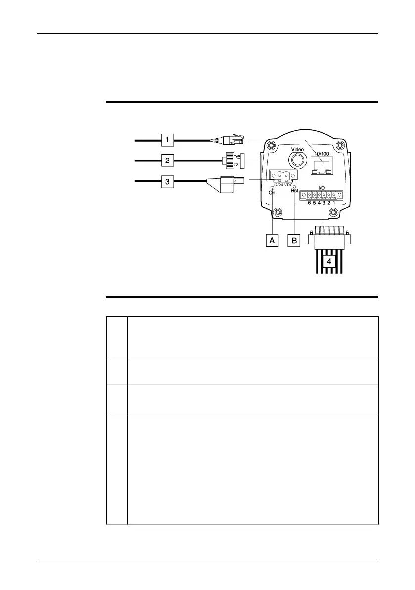
Explanation
This table explains the figure above:
Network cable with an RJ45 connector for Ethernet™ connectivity and PoE™
(dependent on the camera model)
Note: Only CAT-6 Ethernet™ cables should be used with this camera.
1
Video cable with a BNC connector for CVBS (composite video) output
(subject to camera model)
2
Power cable for 12–24 VDC power in
Note: The power connector on the camera is polarity protected.
3
Digital I/O ports, opto-isolated (six-pole screw terminal)
Pin configuration:
1 IN 1
2 IN 2
3 OUT 1
4 OUT 2
5 I/O +
6 I/O –
For a schematic overview of the digital I/O ports, see page 35.
4
22 Publ. No. T559498 Rev. a461 – ENGLISH (EN) – August 19, 2010
 Loading...