Notice to customer
Flir K series In-truck charger
© 2013, Flir Systems, Inc.
#T559801; r. 6533/6533; en-US
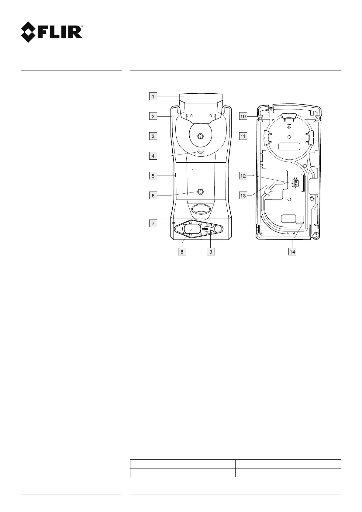
2 Parts and functions
1. Top cover.
2. LED indicator for the camera charger.
3. Hole for attaching the charger housing to the metal bracket.
4. Connectors in the cradle.
5. Connector to power the charger using a standard Flir Systems power supply.
6. Hole for attaching the charger housing to the metal bracket.
7. LED indicator for the battery charger.
8. Battery slot.
9. Eccentric latch to secure the battery during charging.
10. Cable port (1 of 4).
11. Routing support.
12. 12–24 VDC cable plinth.
13. Recess for the cable.
14. Routing support.
3 Choosing a suitable position
Before mounting the in-truck charger, take a few minutes to think about a suitable
position.
The mounting position should be protected from rain and road splash, and it should be
reasonably easy to install a permanent cable running from the fire engine’s 12–24 VDC
system to the in-truck charger.
Additional considerations may be important, e.g., getting access to panels and equip-
ment behind the in-truck charger.
4 Recommended cable area and fuse
Cable area 1.5 mm
2
(No. 15 AWG)
Fuse 5 A
2 (4)
www.flir.com

 Loading...