Operation
5
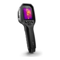
Figure 5.4 Thermocouple temperature readout (33.7℃, in this example)
1. If necessary, enable the thermocouple mode in the menu system (under
Measurement). The thermocouple is enabled when the ‘TC’ label is shown
on the display.
2. Connect a Type-K thermocouple sub-miniature plug (see Figure 5.3) to
the jack in the top compartment.
3. Touch the thermocouple probe tip to the surface under test or hold it in air.
Read the temperature value on the display next to the ‘TC’ label, see Fig-
ure 5–4.
4. Go to General Settings in the menu system to select °C or °F temperature
units.
5. If the thermocouple is not connected when the Type-K mode is selected,
the display will show dashes in place of a reading. If the measurement is
out of range, the display will show ‘OL’.
6. To find the optimum emissivity setting for a given surface, take an IR tem-
perature measurement and then take a Type-K measurement. Adjust the
emissivity until the IR measurement value equals the Type-K measure-
ment value. Now the emissivity is optimised. Emissivity can be set in the
menu system (under Measurement).
#NAS100014; r. AJ/68076/68076; en-US
10

 Loading...