Cleanfix
®
REVERSIBLE FANS
Assembly Instructions
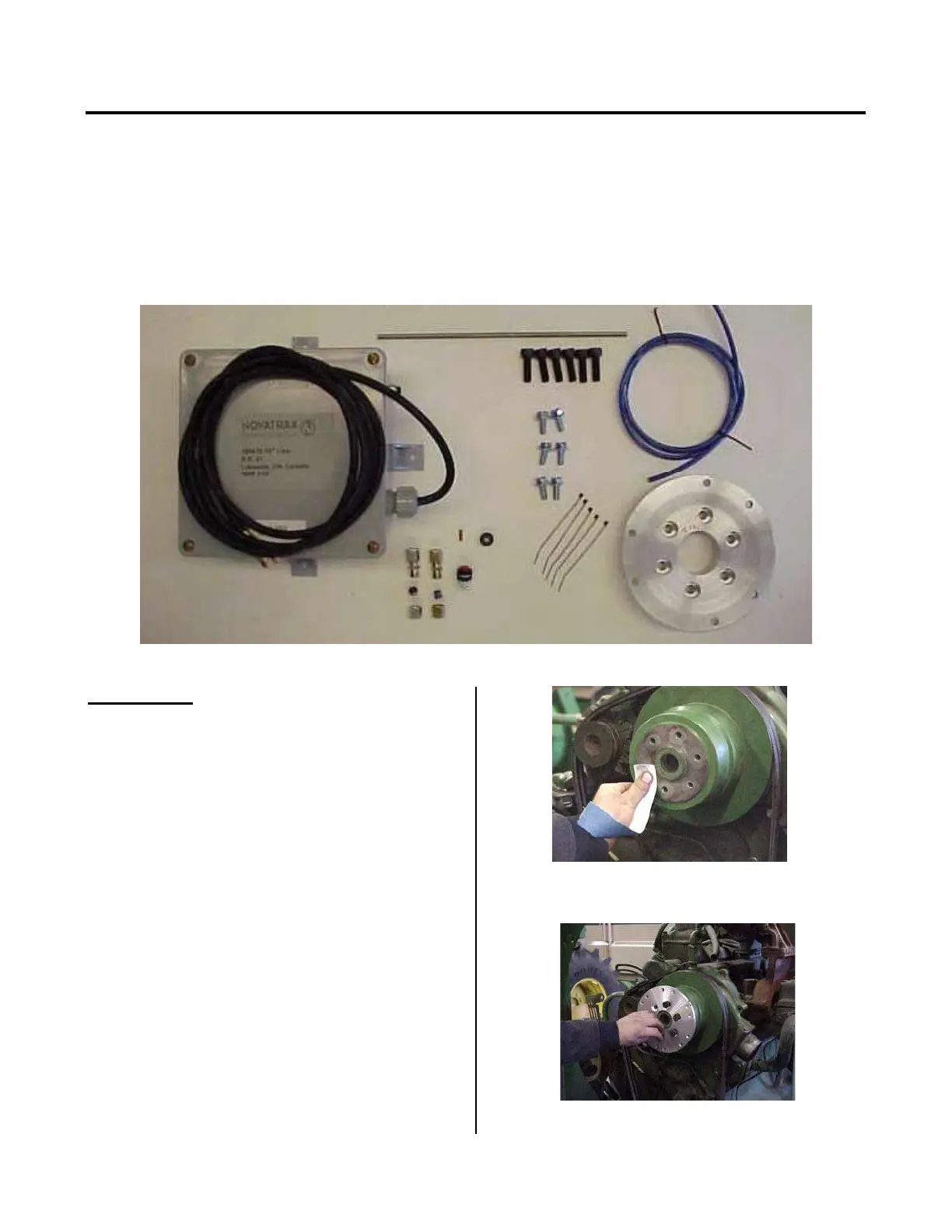
The Cleanfix Fan Kit includes the following components required to install or replace the original equipment fan (refer to
figure 1): Control Box and 10 feet of 2-wire, 14 gage electrical cord (with or without automatic timer), 20 feet of 6-mm air
tube, 1 x brass tube support, 1x compression fitting (steel-to-plastic), 1x compression fitting (steel to steel if required), 1 x
rubber grommet, 1 x 12-inch air tube extension (if required), 6 x M8-1.25 hex bolts, flange mounting bolts (if supplied),
adapter flange to suit fan drive pulley or jack shaft, 5 tie straps and one push button. (Note: components may vary
depending on machine & application.
It is important to check the condition of your equipment’s fan belt prior to installing the Cleanfix Fan. Worn or damaged
fan belts should be replaced at this time for ease of access during assembly.
Figure 1 – Components required for installing the Cleanfix Reversible Fan
FAN POSITION
The ideal fan position for the Cleanfix Reversible fan is
listed below:
- Suction Fan: 2/3 of blade tip into shroud & 1/3 out of
shroud.
-Blower Fan: 1/3 of blade tip into shroud & 2/3 out of
shroud.
This may vary depending on the application
STEP 1 - Before installing the fan, be sure that the engine
is turned off and the positive battery terminal is
disconnected.
STEP 2 - Remove the original OEM fan. Refer to the
manufacturer’s equipment manual. Check the water
pump or fan mounting bearing to ensure that it is in good
condition, replace it if necessary.
STEP 3 - Clean the pulley surface if necessary with
sandpaper to create a smooth and clean mounting
surface for the Cleanfix Fan adapter flange.
NOTE: There should be not dirt or debris remaining on
the pulley including inside the center mounting stud as
shown (Figure 2).
FIGURE 2
STEP 4 - Place the adapter flange onto the fan drive
pulley locating it using the center pilot hole (Figure 3).
FIGURE 3
122
 Loading...