Cleanfix
®
REVERSIBLE FANS
STEP 5 – Set up dial indicator gauge to measure axial
and radial deviation. Rotate the flange clockwise taking
readings from both the front face and the top edge of the
flange (Figure 4). The maximum variance must not
exceed 0.004 inch. or 0.10 mm. If you are unable to
obtain suitable results remove the flange and clean the
pulley surface with sandpaper again. Repeat STEPS 3 to
5 again until correct.
FIGURE 4
STEP 6 – Install the adapter flange to the pulley, using
bolts supplied with kit. Tighten to the maximum torque as
indicated in the manufacturers' equipment manual.
NOTE: Use Blue Loctite on each bolt to fasten the
flange to the fan drive pulley, to prevent the bolts from
coming loose during operation.
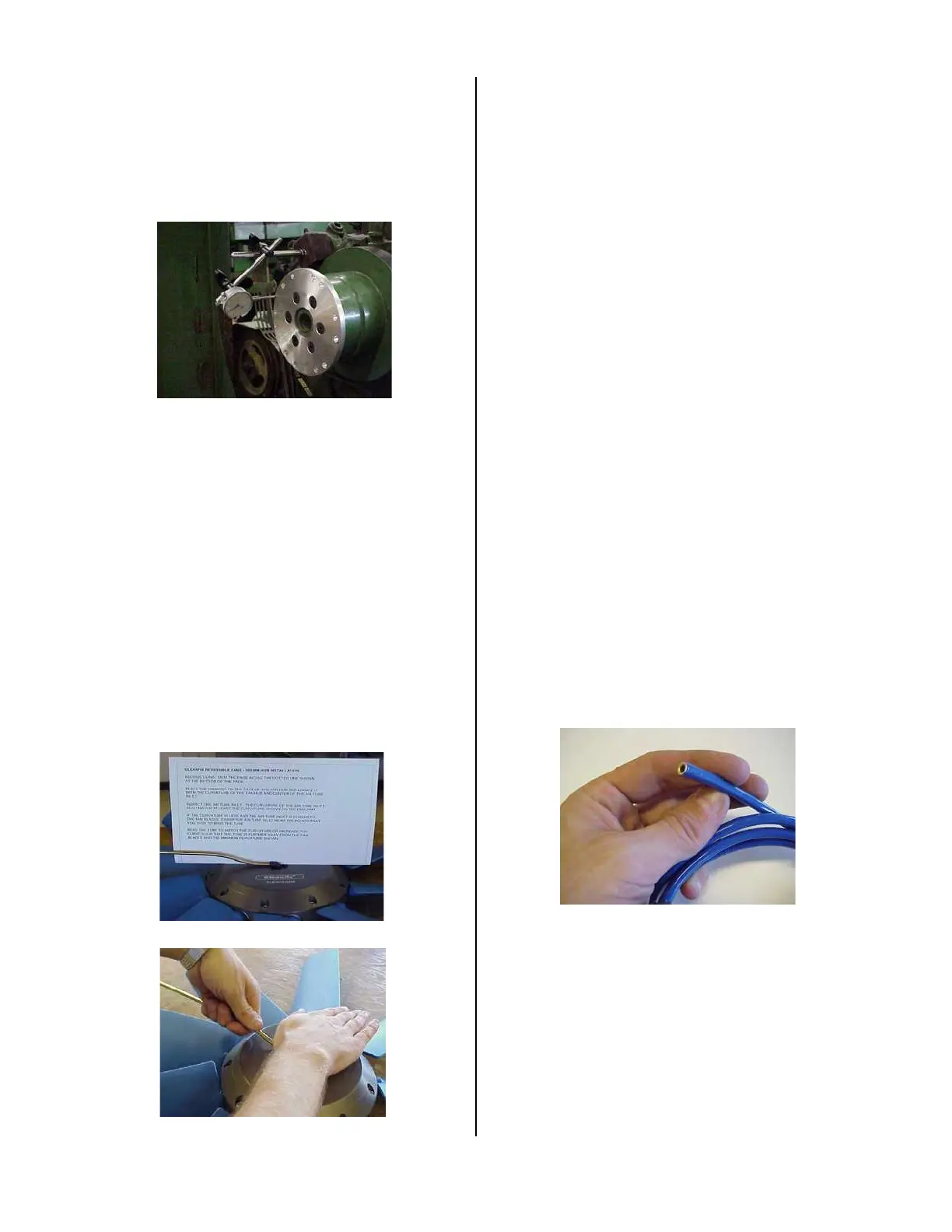
STEP 7 – Check the curvature on the air tube supply line.
Using the gauge supplied, follow the directions to ensure
that the fan inlet has not been bent during shipping
(Figure 5A). NOTE: The air inlet tube must match or
exceed the minimum curvature shown for safe operation
of the Cleanfix Fan. In the event that the curvature is less
than the curvature shown on the gauge, carefully grasp
the tube with both hands while securing the base of the
air tube inlet with your palm at the center of the fan hub
(Figure 5B). Apply force to bend the tube to the required
curvature. Re-check the curvature with the gauge until
correct.
FIGURE 5A
FIGURE 5B
STEP 8 - Connect the supplied steel to steel compression
fitting to the air tube inlet on the fan. NOTE: Small
diameter fan will not require an air tube extension or the
steel to steel compression.
IMPORTANT - This compression fitting must not be
confused with the compression fitting used to connect the
plastic air tube to the steel air tube extension. You can
tell the difference between the two compression fittings by
inspecting the internal furl. The steel to steel
compression fitting does not contain a rubber seal.
STEP 9 - Connect the steel air tube extension to the air
tube inlet using the steel to steel compression fitting. The
air tube extension should be used to extend the inlet tube
far enough to reach the outer diameter of the fan but must
remain at least 1-inch from the inside surface of the
radiator shroud (i.e. not to penetrate or touch the
shroud).
STEP 10 - Inspect the air tube inlet to determine where
you plan to have the plastic air tube penetrate through
the fan shroud. Drill a hole through the shroud which is
large enough for the supplied grommet, where the plastic
air tube will penetrate. This location is best set at either 3,
6 or 9 o’clock positions in order to allow for ease of
installation. Ensure that the hole is large enough to allow
the air tube to move freely into the shroud when the
engine is torqued without getting caught. NOTE: The
plastic air tube should be secured with tie straps such that
it cannot be pulled into the shroud where it will become
entangled with the rotating fan (see STEP 17).
STEP 11 - Cut the end of the plastic air tube to make it
flat if necessary. Insert the brass tube support into the
plastic air tube. Note this may have been completed at
the factory (Figure 6).
FIGURE 6
STEP 12 - Connect the air-supply tube to the air tube
assembly using the supplied steel to plastic compression
fitting (Figure 7). NOTE: For small diameter fans, the
steel to plastic compression fitting will connect directly to
the air tube inlet. The hose end with the brass tube
support must be placed into the compression fitting to
prevent the tube from collapsing inside.
123
 Loading...