Cleanfix
®
REVERSIBLE FANS
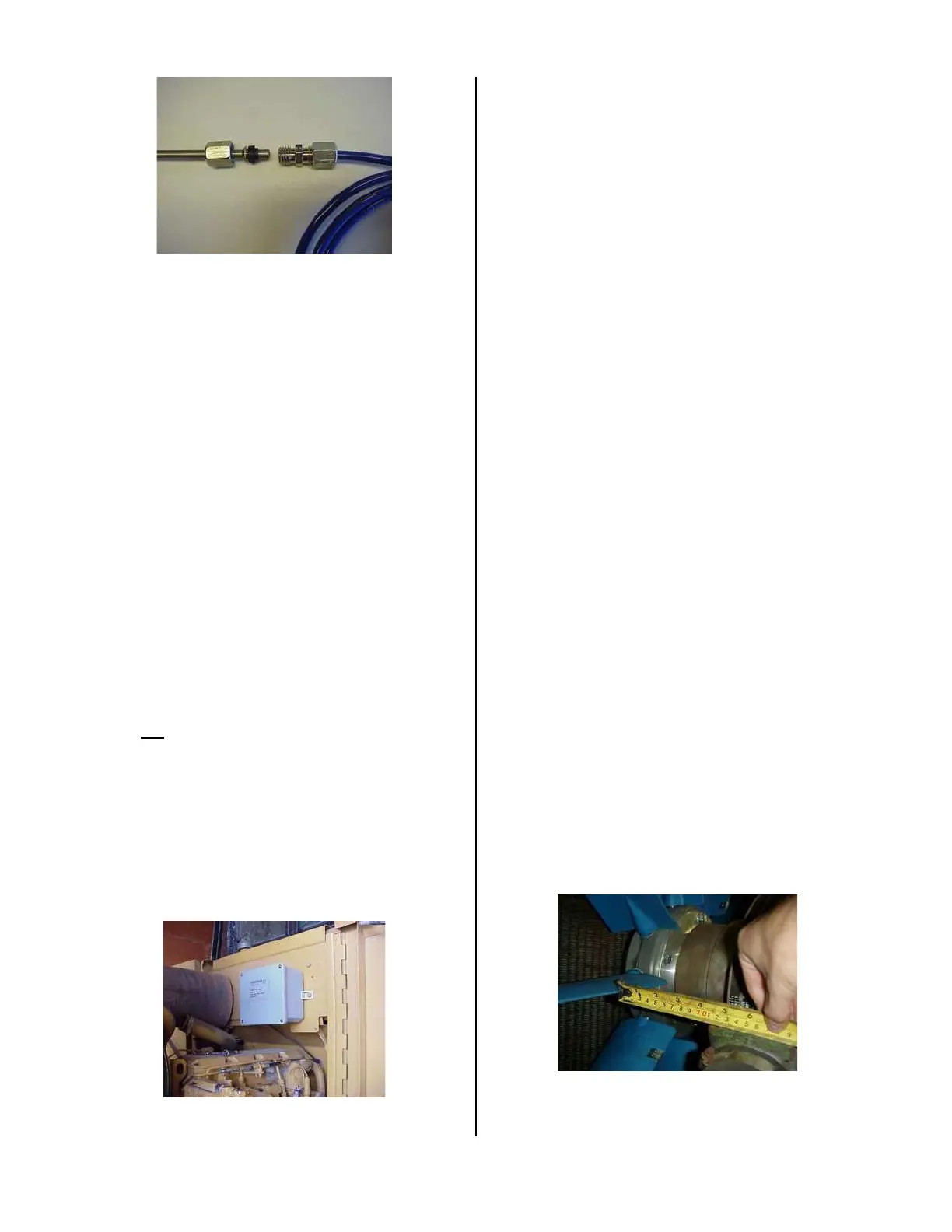
FIGURE 7
Warning: Do not secure the air lines in any way that will
cause a side load or leverage to be applied to the steel
inlet line of the fan. Bearing failure may result is the
precaution is not followed.
STEP 13 - Mount the Cleanfix Fan onto the adapter
flange using the 6- M8 hex bolts that are supplied while
ensuring that the plastic air tube penetrates through the
shroud in the hole that was previously made in STEP 10.
IMPORTANT - Be sure to install the mounting bolts using
Blue Loctite, and be sure the belt(s) are in place before
mounting the fan.
STEP 14 - Drill a hole in any shields that may prevent you
from running the air tube to the control box. The hole
should be large enough to fit the rubber grommet that is
supplied. Insert the rubber grommet into the hole that you
have drilled. Insert the hose through the rubber grommet
to prevent the hose from wearing through the surface
where it contacts the shield.
STEP 15 - Mount the control box as shown in the engine
compartment where room will allow using the 4 mounting
clips on the backside of the box. The location chosen
should not be close to the exhaust manifold from the
engine in order to prevent excessive temperatures from
developing inside the control box. If room is unavailable
in the engine compartment, it may be necessary to mount
the control box inside of the operator’s compartment or in
a convenient location (Figure 8). The location chosen
should be solid to prevent unnecessary vibration and
allow for good connection of the control box to the
surface. Use Blue Loctite on each of the mounting bolts
to help ensure that the bolts do not come loose during
operation.
FIGURE 8
STEP 16 - Connect the air tube to the quick connect on
the side of the control box and test the connection by
pulling on the air tube to make sure that it does not come
out. To release the air tube from the control box, press
the plastic ring on the connector towards the box and
then pull the air tube away from the box with your other
hand. The air tube should release. If it will not release
there may still be air pressure in the line. Release the air
pressure from the air tube and repeat the above steps.
STEP 17 - Secure the air tube with the supplied tie straps.
All air lines, hydraulic hoses, radiator overflow tubes and
electrical wires that are in the area of the fan must be
secured in order to prevent them from being sucked into
the fan blades when the fan reverses the airflow direction.
Failure to do so, may result in damage to the Cleanfix
Fan or the equipment’s cooling system.
STEP 18 - Run the power supply wire into the operator's
compartment and connect the supply to the ignition
switch using a fused circuit. (see electrical diagram for
proper circuit size). (Ensure the power supply is
connected to a dedicated (separate) key powered source
& correct amperage and voltage is available during
operation). Using the same electrical wire, connect the
override push button as shown in the supplied electrical
schematic.
STEP 19 - Before tightening the fan belts or starting the
engine, cycle the fan to ensure that it will operate without
restrictions or interference from the surrounding
components. Obstacles such crankshaft dampener, belt
tension pulley, or the air tube inlet on the front of the fan
may create interference and prevent the fan from rotating
into the cleaning position. Connecting the air inlet tube to
the shop air supply can allow you to move the blades
back and forth through the cleaning and cooling position.
With the fan belt(s) loose, rotate the fan with the blades in
the mid position to ensure that no obstacles will come in
contact with the fan blades during the pitch change from
the cooling position into the cleaning position. There
should be a minimum of 5/8” (15-mm) clearance between
the fan blades in mid position and any obstacles for safe
operation of the Cleanfix Fan (Figure 9).
FIGURE 9
124


 To Next Page
 Loading...
