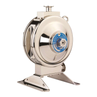
The Flotronic 'One-Nut' Pumps Diaphragm Leak Detection System is designed to monitor Flotronic Double Diaphragm pumps for diaphragm failure, which could lead to contamination of the pumped product, the pump's internal air control systems, or the surrounding area. The system aims to prevent such contamination by detecting leaks and stopping the pump's operation.
Function Description:
The leak detection system consists of two capacitive sensors and a main control unit. The sensors are mounted on the pump, one per air chamber, and continuously monitor the air chambers for the presence of foreign material other than air. These capacitive sensors detect changes in a self-generated capacitive field, allowing them to function correctly with most pumped substances, regardless of whether the media is conductive or transparent. A key feature of these sensors is their ability to sense through a protective PTFE housing, preventing direct contact with aggressive pumped media while still detecting leaks.
Upon sensing a diaphragm failure, the main control unit activates a customer-supplied solenoid valve in the pump's air supply line, stopping the pump. A flashing red LED on the main control unit indicates the fault. The system latches into an alarm condition until the failure is cleared and the unit is reset by pressing the front panel-mounted Reset button. If the pumped media is still contaminating the sensors, the unit cannot be reset until the fault is rectified. In the event of a power failure to the main unit, the pump defaults to an "off" state and remains stopped until power is restored and the Reset button is pressed. The main control unit also alarms and sets to a fail condition if the sensors are not connected or if they fail to operate within their normal parameters.
The system includes a volt-free relay connection that can be wired for either normally open or normally closed configurations upon an alarm state. This connection can be used to monitor the unit's state (running or fault) or to control other equipment dependent on the pump's status. To fully comply with the 3A standard, a solenoid valve must be connected to the main control unit to stop the pump upon detecting a failure. This solenoid valve should be fitted to the air pipe supplying the pump.
Important Technical Specifications:
Main Control Unit:
- Input Voltage Range: 96-264Vac, 50/60Hz
- Operating Temperature Range: 0 - 40°C
- IP Rating: IP65
- Maximum Power Consumption: 30 Watts
Sensors:
- Maximum Sensor Pressure: 7.2 Barg (105psi)
- Sensor Temperature Range: -25°C - 85°C
- IP Rating: IP67
- Sensor Lead Length: Varies
Solenoid Valve (Customer Supplied):
- Type: Normally Closed
- Voltage: 24Vdc
- Maximum Power Rating: 16 Watts
- IP Rating: Depending on customer requirements, minimum recommended IP65. The solenoid valve should be rated for continuous energization.
Volt Free Relay Connection:
Usage Features:
- Simple Operation: During normal operation, only the 'Power' LED on the main control box is continuously lit. A fault is indicated by a flashing 'Fault' LED and the pump stopping.
- Reset Functionality: After a fault is rectified, the system can be reset by pressing the 'Reset' button. The system will not reset if the fault (e.g., contamination) is still present.
- Power Interruption Safety: If power to the main control unit is interrupted, the pump stops and requires a manual reset via the 'Reset' button to restart.
- Wiring Connections: The main unit has sockets for sensors and the solenoid valve. Mains power connection is via a hard-wired lead with a socket and plug. Solenoid valve, volt-free relay, and mains power connection plugs are user-connectable via internal screw terminals.
- Electrical Safety: The unit MUST be earthed/grounded. Electrical installation should be performed by a qualified electrician in compliance with local codes. Power must be removed before connecting or disconnecting cables.
Maintenance Features:
- Sensor Cleaning: In case of a diaphragm failure, the sensor housing needs to be cleaned to remove all traces of product that might prevent the system from resetting. This involves unplugging sensors, removing air domes, cleaning the sensor port inside the air dome, drying the port, and then rebuilding the pump with replaced failed components. If contamination is difficult to remove, the PTFE sensor housing can be unscrewed from the air dome for better access, ensuring the metal sealing ring is correctly positioned upon re-assembly.
- Maintenance Precaution: Always disconnect the power supply from the control box before any maintenance or cleaning operation. Ensure cleaning solutions are compatible with the items being cleaned and avoid harsh chemicals on the exposed sensor section outside the pump.
- System Function Test: The system's proper function should be checked every 3 months or earlier if a problem is suspected. This involves:
- Disconnecting power and air supply to the pump.
- Unplugging sensors from the main control unit.
- Unscrewing PTFE sensor housings from air domes.
- Reconnecting sensors and power to the main control unit.
- Ensuring sensor housing faces are clear of obstructions.
- Resetting the main control unit. The 'Fail' LED should turn off, and the 'Power' light remain on.
- Placing a hand near a sensor housing to simulate a fault; the main control unit should register a fault, and the 'Fault' LED should illuminate. Repeat for the other sensor.
- Pump Shut Down Check: After confirming sensor function, reassemble the pump and perform a shut-down check:
- Connect power and turn on air supply. The pump should not start, and the red LED should be flashing.
- Press the Reset button; the pump should start, and the fault LED should go off.
- Disconnect power; the pump should stop. This confirms correct function of sensors, main control unit, and solenoid valve.
- Troubleshooting Guide: The manual provides a troubleshooting table for common issues like "Power LED not illuminated," "Fault LED flashing," "Pump does not stop when fault LED is flashing," and "Pump does not run," outlining probable causes and solutions. For persistent issues, contact Flotronic Pumps Ltd.
- Main Control Unit Maintenance: The main control unit requires no routine maintenance. If a fault is suspected, Flotronic Pumps Ltd should be notified, and the unit may need to be returned for investigation.