Valve Threaded Ends:
Thread standard is either ISO 228, which is a
straight metric thread (compatible with BS-2779)
or NPT threading standard, depending on the
product number ordered.
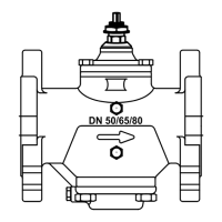
Valve Flanged Ends:
Flange ends are compatible with DIN steel flang
-
es PN10, PN16, PN25 and/or PN40 according to
EN1092-1 or ANSI steel flanges class 150 and/
or 300 according to ASME B16.5. depending on
product ordered.
Flanges are not supplied by FlowCon.
FLOWCON VALVE ACCESSORIES:
Two different types of pressure/temperature fit-
tings (p/t plugs) are available upon request for
valves with body tappings, i.e. p/t plugs with
-
out collar and p/t plugs with collar. Suitable
p/t plug choice will depend on the valve. Alterna
-
tive to p/t plugs, the valve body can be ordered
with plugs for the body tappings. Extended p/t
plugs (without collar) are standard included with
FlowCon AHU and FlowCon Wafer.
Before finger mounting p/t plugs without collar in
the body tappings (DO NOT OVER TIGHTEN),
please seal the threads of the p/t plugs. Thread
sealing is described elsewhere in this General
Instruction. P/t plugs with collar as well as plugs
are sealed by a gasket. After finger mounting,
gasket sealing requires 1-3 Nm torque.
Threaded union end connections (male or fe
-
male) for union end connected valves must have
the union nuts and the end connections should
be removed for installation.
Soldered union end connections (sweat) for
union ned connected valves must have the END
CONNECTIONS REMOVED FROM THE HOU-
SING BEFORE SOLDERING. THIS ENSURES
THAT THE O-RINGS AND INTERNAL PARTS
ARE NOT DAMAGED BY HEAT.
Capillary tubes are not to be damaged.
Therefore, do not force the tube to compress or
bend with a bending radius below 20 mm (3/4”).
Capillary tube for inserts (ACC00110)
Capillary tube is supplied with fixed M8 fitting
and O-ring at each end. Ensure that the O-ring
is greased and correctly placed before finger
mounting the capillary tube in the FlowCon
QuickDisc
®
(DO NOT OVERTIGHTEN AS THIS
WILL DAMAGE THE O-RING). If the capillary
tube is to be mounted in a FlowCon Partner Ball
or other valve with 1/4” (ISO 7/1) tapping, a 1/4”
to M8 adaptor is available (ACC00121). Thread
sealing and O-ring lubrication are described else-
where in this General Instruction.
Capillary tube for PIM-DP (F212)
Capillary tube is supplied with fixed angled
1/4” NPT fitting (F4039-14) at one end going
to the FlowCon Partner Globe with an adaptor
(ACC6584). The other tube end is to be as
-
sembled in the 1/4” NPT fitting already mounted
on the FlowCon PIM-DP. Thread sealing is de
-
scribed elsewhere in this General Instruction.
FLOWCON INSERTS:
Please see specific installation instruction for
selected insert (Green, EVS, E-JUST, Composite,
Stainless Steel, SDP, EDP, ADP or T-JUST) re-
garding valve housing match, installation and
setting.
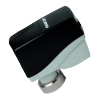
FLOWCON ACTUATORS:
Please see specific installation instruction for se-
lected actuator (EV, FT, FN, FH, SM, BB or T)
regarding product fitting, mounting position and
wiring. For product match please read FlowCon
Actuator Matrix.
FlowCon General Instruction
1B95011 - 01/2019
Latest release of any FlowCon material is available on www.owcon.com
Page 3 of 4
 Loading...