Do you have a question about the FlowCon FN.0.2 and is the answer not in the manual?
Do not connect power before fitting the actuator or install in closed position to prevent valve damage.
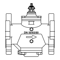
Mount actuator on valve and finger tighten the connection union. Do not use additional tools.
Electrically open actuator via DIP switch #6 (FN.0.2/FN.0.4) or retract spindle (FN.0.2-BUS) before loosening union.
Upside-down installation is permitted along with standard horizontal and vertical orientations.
Wiring details for FN.0.2 0-10V modulating actuator, including input and feedback signals.
Wiring diagram for FN.0.2-BUS actuator using RS-485 serial communication (D+, D-, P1, P2).
Wiring for FN.0.4 2-Position (Normally Closed) and 3-Point Floating (Normally Closed) actuators.
Actuator calibrates to closing point upon power-up, then enters normal operation mode.
Prevents valve jamming by performing 50% stroke cycle every 3 weeks if no movement occurs.
Activates valve full opening via DIP switch #6, indicated by blinking red/green LED.
Allows manual valve operation (open/close) using a magnet on the actuator's right side.
Temporarily opens valve fully, independent of control signal, for system flushing.
Configuration of DIP switches #1-6 for FN.0.2 functions like override, signal type, and auto cycle.
Settings for FN.0.2-BUS DIP switches #1-8 for Modbus/BACnet, BIT settings, and terminal resistor.
LED indications for FN.0.2: green (normal), blinking green (calibration), blinking red/green (override), red (failure).
LED indications for FN.0.2-BUS: green (normal), flickering green (bus comms), blinking yellow (manual spindle).
LED indications for FN.0.4: green (normal), blinking green (calibration), blinking red/green (override), red (failure).
Forced re-calibration via DIP switch #6 toggle or electrical 10V-2V signal sequence.
Re-calibration via BACnet (MSV.1=2) or Modbus (register 138=1).
Forced re-calibration via DIP switch #6 toggle.
Setting Baud Rate, DIP switches, MAC address, and selecting PICV valve type and control mode.
Checking Current Flow, Status Information, Error Information, and service commands via bus.
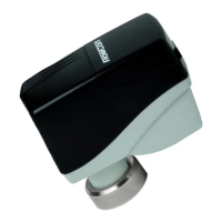
The FlowCon FN.0.2, FN.0.2-BUS, and FN.0.4 are electrical actuators designed for precise control in HVAC systems. These actuators are part of the FlowCon International product line, manufactured by Griswold Controls LLC./FlowCon International Company.
The FlowCon FN.0.2 is a 24V modulating actuator, providing continuous control based on an input signal. The FN.0.2-BUS is also a 24V modulating actuator but includes Modbus or BACnet communication capabilities, allowing for integration into building management systems (BMS). The FN.0.4 actuator offers 24V 3-point floating and 2-position control, suitable for applications requiring simpler on/off or incremental adjustments.
FN.0.2 Actuator (Analog):
FN.0.2-BUS Actuator (RS-485 Serial):
FN.0.4 Actuator (Digital):
Fitting and Re-fitting:
Orientation:
Start-up Sequence:
Auto Cycle Sequence:
Electrical Override:
Manual Override (FN.0.2-BUS):
Flush Mode (FN.0.2-BUS):
DIP Switch Settings:
LED Status:
This paper serves as a supplement to the FlowCon General Instruction. The latest release of any FlowCon material is available on www.flowcon.com. FlowCon International assumes no responsibility for mistakes, if any, in any printed material.
| Brand | FlowCon |
|---|---|
| Model | FN.0.2 |
| Category | Controller |
| Language | English |