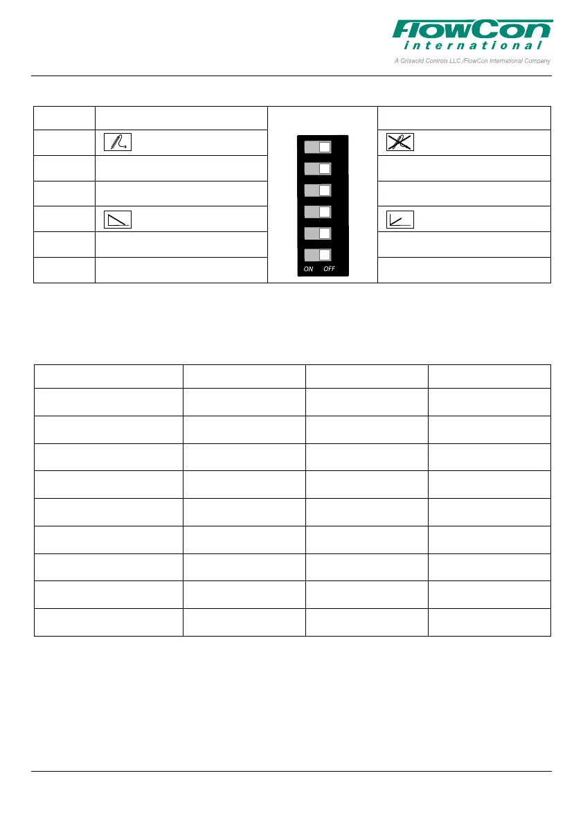
DIP
switch
Function ON Function OFF
#6 Electrical override ON Electrical override OFF
#5 No function No function
#4 No function No function
#3 Normally Open Normally Closed
#2 No function No function
#1 No function No function
6
5
4
3
2
1
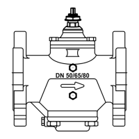
FlowCon FN.0.4 Actuator
FN.0.2 FN.0.2-BUS FN.0.4
Normal operation mode Full on green Full on green Full on green
Charging mode (60 sec) n/a n/a n/a
Calibration mode
(closing point adjustment)
Blinking green Blinking green Blinking green
Bus communication mode n/a Flickering green n/a
Mounting position mode n/a Rapid blinking green n/a
Electrical override mode Blinking red/green n/a Blinking red/green
Failsafe mode n/a n/a n/a
Manuel spindle adjustment n/a Blinking yellow n/a
Perpetual failure mode Full on red Full on red Full on red
LED Status
The LED indicator is visible through the dark colored transparent connection cover.
The LED indication will give the following statuses.
FlowCon FN.0.2, FN.0.2-BUS and FN.0.4
1B95080 - 01/2023
This paper is a supplement to the FlowCon General Instruction
Latest release of any FlowCon material is available on www.owcon.com
Page 5 of 8