Do you have a question about the FlowCon SM Series and is the answer not in the manual?
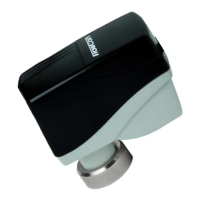
Instructions for mounting the actuator onto the valve spindle, including O-ring greasing and snap ring engagement.
Details on allowed installation positions: upside-down, horizontal, and vertical.
Diagrams and explanations for analog and digital FlowCon SM actuator wiring.
Procedure for automatic valve calibration and initial operation modes.
Guide to accessing and navigating the actuator's programming menu.
Configuration of password, language, valve model, units, flush mode, and control signal type.
Setting minimum/maximum values, feedback, flow, rotation, mode, password activation, and failsafe direction.
Explanation of actuator display elements (indicators, values) and information codes.
Accessing and understanding actuator alarm codes, icons, and their meanings.
Instructions for auto-stroke sequence, manual override, and failsafe mode.
Guidelines for system flushing, valve installation orientation, and thread sealing.
O-ring greasing, pressure limits, and conditions that void warranty.
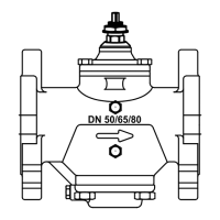
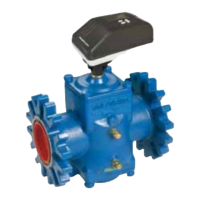
Description of various FlowCon valve housing types and their connection options.
Details on end connections, p/t plugs, capillary tubes, and references for inserts/actuators.
| Brand | FlowCon |
|---|---|
| Model | SM Series |
| Category | Controller |
| Language | English |