Information
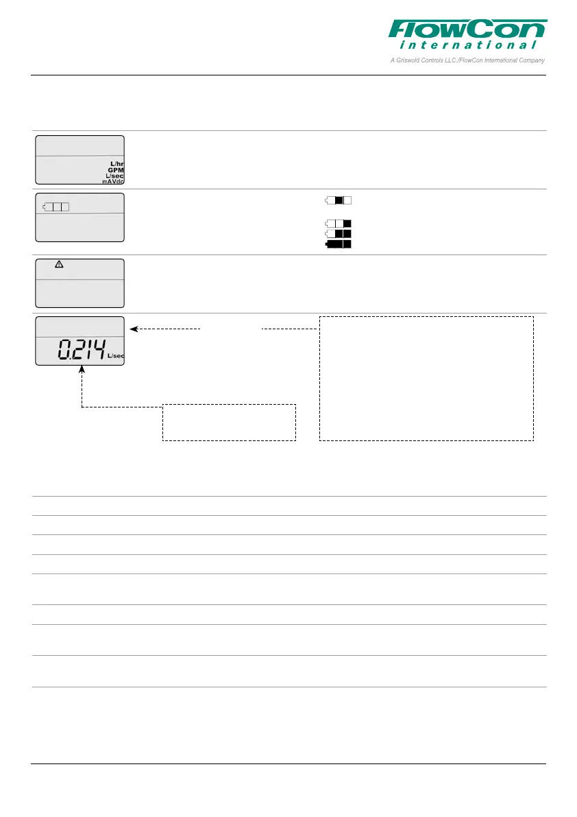
Current flow rate
1
.
Indicates current flow rate in
l/sec, l/hr or GPM.
Display Description Values
Indicates unit scale system. l/sec or l/min or GPM.
mA or VDC.
Indicates battery level. Basic version with no battery (SM.0.0.0.3)
Failsafe version with battery (SM.0.0.0.4)
Battery level low, charging needed.
Medium battery level.
Battery charged.
Alarm indicator. Blinking if actuator is still functional (warning).
Fully on if actuator is not working (critical).
CONTROL SIGNAL 2.0 VDC
FEEDBAC SIGNAL 2.0 VDC
VALVE SM. 3.1
pressur range 30-800 kpad
MAXIMUM FLOW RATE 6.580 L/SEC
OPERAT DIRECT NC
ACTUAT.MODE LIN flo
FAIL SAFE DIRECT CLOSE
ERROR CODE 01
Information
Control signal Indicates value of control signal. 0-10 VDC or 0-20 mA or Open/Stop/Close
Feedback signal Indicates value of feedback signal. 0-10 VDC or 0-20 mA
Valve Indicates valve model. SM.1.1, SM.2.1...
Pressure range Indicates pressure range. 32-320 kPaD, 40-320 kPaD.....
Maximum flow rate Indicates selected maximum de
-
signed flow rate.
Depends on valve etc.
l/sec, l/hr or GPM
Operational direction Indicates direction of rotation. NO or NC
Actuator mode Indicates control mode Linear flow, Equal percentage, Linear rotation or
Linear signal
Failsafe direction Indicates failsafe direction. Open or Closed
Valid for failsafe actuator models
Critical Alarm Indicates alarm error code. 01, 03, 05 (without failsafe) or 06.
Only if critical alarm is present.
In Operation
Note 1: The flow rate shown on the actuator display is a calculated value. Flow rates below 1.0 valve rotation is shown as indications,
illustrated with an apostrophe in front of the flow rate. If display shows “NA” the valve model has not been chosen in programming menu step 2.
Use
to go to next information line and
to go
to the previous.
This paper is a supplement to the FlowCon General Instruction
Latest release of any FlowCon material is available on www.owcon.com
FlowCon SM 15-250 mm (1/2”-10”)
1A95106 - 01/2019
Page 6 of 8
 Loading...