Argus
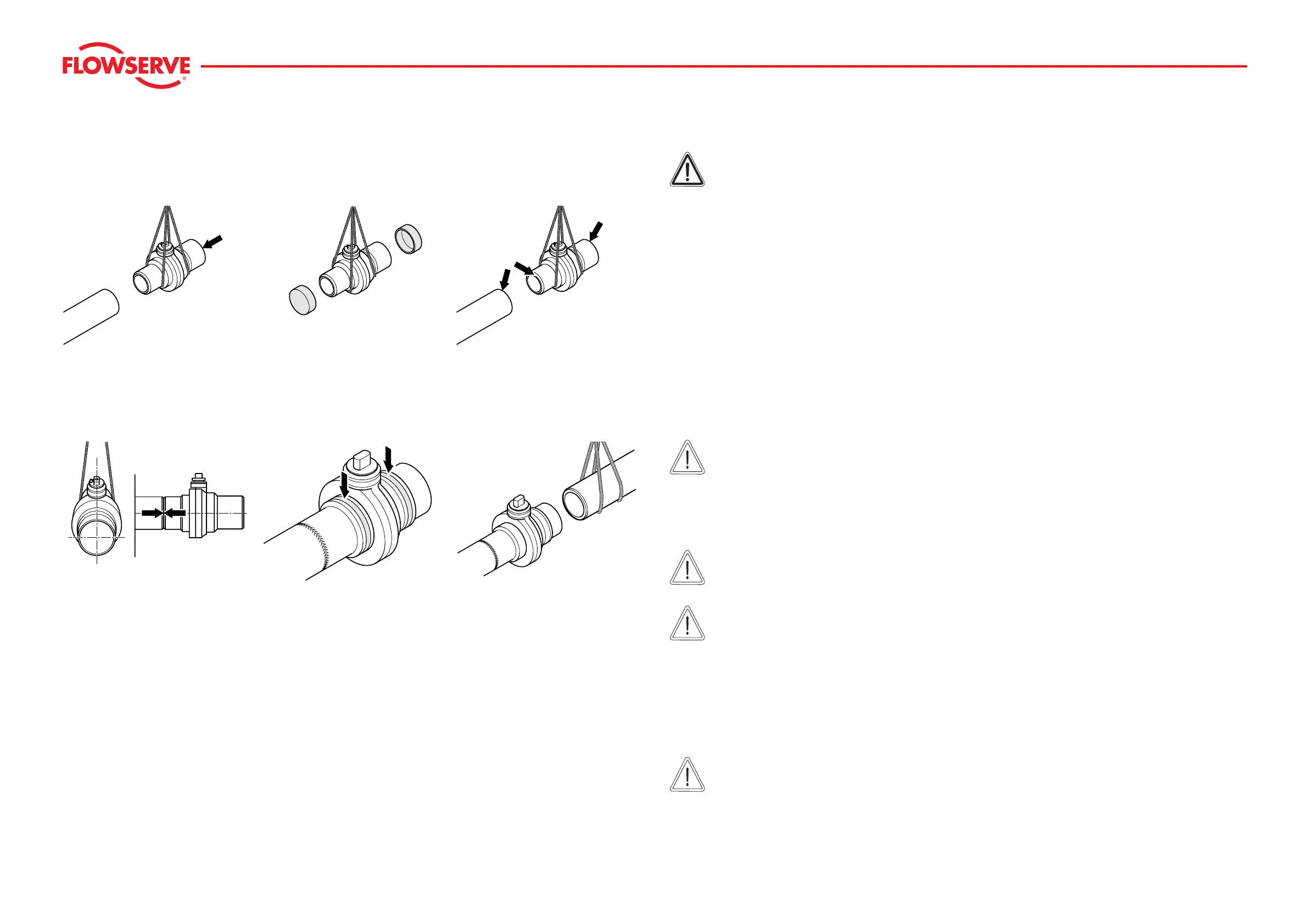
Installing the Welding Connection
8
Installing the Welding Connection
Installing the Ball Valve
0002-00-002 0002-00-004 0002-00-001
Welding the Connections
0003-00-003 0002-00-006 0003-00-005
Danger!
The local welding regulations and specifications must be complied with when carrying out welding
work.
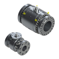
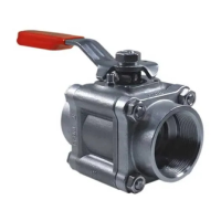
f Transport the ball valve to the installation site using suitable hoisting gear dimensioned in accordance
with the weight and size of the ball valve (Figure 0002-00-002).
f Remo
ve the protective caps (Figure
0002-00-004).
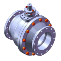
f Clean the pipeline and connecting socket (Figur
e
0002-00-001).
f Remo
ve any paint and rust around the weld area on the pipe and welded end of the ball valve.
Ensure that a bright metal surface is obtained.
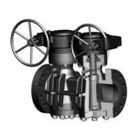
f Check that the ball valve is correctly positioned and aligned with the pipeline.
The permissible tolerances and specifications in accordance with the agreed proposed use for the ball
valve must be complied with (Figure
0003-00-003).
Due to the short length of the welded ends, there
is a risk that the soft inserts may be destroyed during the
welding work.
Caution!
Use temperature measuring strips to check that the temperature does not rise beyond the
permissible limits (100°C). The strips must be fitted to the connection near the soft inserts
(Figure
0002-00-006).
These temperature measurement strips are designed so that, when a typ
e-dependent temperature is
reached, the colour irreversibly changes from white to black.
Caution!
The temperature measurement strip must be monitored constantly throughout the welding work.
Caution!
If any change of colour is noticed, the welding work must be interrupted immediately and the weld
allowed cooling.
The temperature measurement strips can be stored at temperatures up to + 35 °C for an unlimited period of
time and are resistant to oils, greases, water and steam.
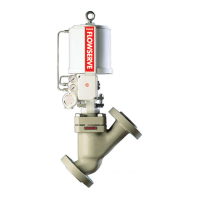
f Connect the second socket in the same way as the first one, as described before
(Figure 0003-00-005).
f After installa
tion, check for any leaks.
Caution!
Before start-up of the ball valve, the pipeline must be rinsed.