2
Description
This P-200 seal is a dual, cartridge mounted, end face mechanical seal,
designed for ease of installation. No seal setting dimensions are
required. Removable setting devices provide proper alignment. Installa-
tion according to the following steps will ensure a long trouble-free life
of the P-200 seal.
1 Equipment Check
1.1 Follow plant safety regulations prior to equipment disassembly:
• Lock out motor and valves.
• Wear designated personal safety equipment.
• Relieve any pressure in the system.
•ConsultplantMSDSlesforhazardousmaterialregulations.
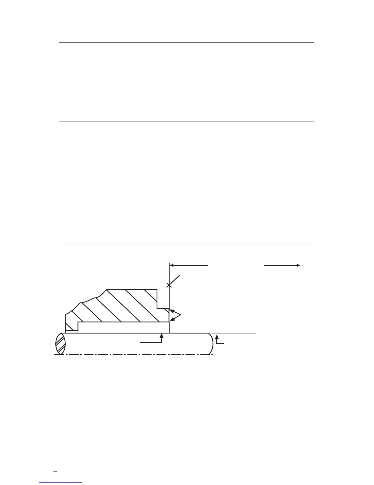
Seal Chamber Requirements Figure 1
To first obstruction
Shaft or sleeve OD
+0.000 mm (+0.000 inch)
-0.050 mm (-0.002 inch)
+0.000 mm (+0.000 inch) API 610/682
-0.025 mm (-0.001 inch) DIN/ISO
ASME
Seal housing face to have surface finish
of 1.6 μm (63 μinch) R
a
finish or better.
Gland pilot can be at either
of these register locations.
Seal housing bore to have 3.2 μm
(125 μinch) R
a
finish or better.
Sleeve or shaft finish to be
0.8 μm (32 μinch) R
a
or better.
The images of parts shown in these instructions may differ visually from the actual
parts due to manufacturing processes that do not affect the part function or quality.
 Loading...