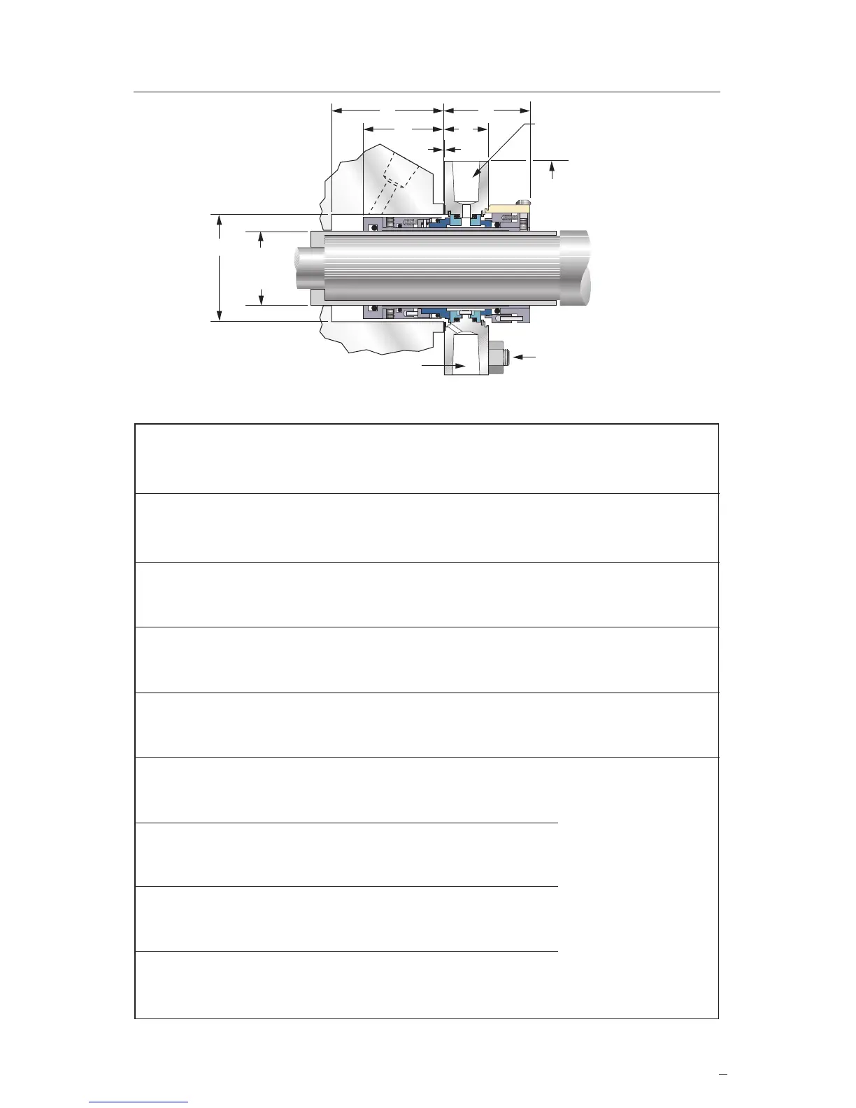
Dimensional Data for P-200 Seal (inches)
3
P-200 Dimensional Data
Figure 2
*ThissealsizeusestheN-CBRinnersealrotaryunit.
†Preferreddesignfortheseshaftsizes.Usewheneverpossible.
.03
A
Shaft & Seal
Size
C
B
K
ø
D F
E
G
NPT marked "Flush" should be
plugged when not used for flushing
4 H
ø studs
equally
spaced on J
2 G
NPT for
sealing fluid inlet
and outlet.
1.000 1.750 1.875 1.78 1.69 2.00 1.02 0.375 0.375 2.75 3.75
1.125 1.750 2.000 1.78 1.69 2.00 1.02 0.375 0.500 3.00 3.88
1.250 2.000 2.125 1.97 1.88 2.00 1.02 0.375 0.500 3.12 4.25
1.375 2.000 2.250 1.97 1.88 2.00 1.02 0.375 0.375 3.25 4.25
1.500 2.250 2.500 1.97 1.88 2.00 1.02 0.375 0.375 3.75 4.75
1.625 2.375 2.625 1.97 1.88 2.00 1.02 0.375 0.500 3.75 4.75
1.750 2.500 2.750 1.97 1.88 2.00 1.02 0.375 0.500 3.75 5.00
1.875 2.625 2.875 1.97 1.88 2.00 1.02 0.375 0.500 3.88 5.00
2.000 2.750 3.000 1.97 1.88 2.00 1.02 0.375 0.625 4.12 5.12
2.125 2.875 3.250 1.97 1.88 2.00 1.02 0.375 0.625 4.38 6.00
2.250 3.000 3.375 1.97 1.88 2.00 1.02 0.375 0.625 4.62 6.50
2.375 3.250 3.625 2.16 2.06 2.09 1.11 0.375 0.625 5.00 6.38
2.500 3.375 3.750 2.16 2.06 2.09 1.11 0.375 0.625 5.00 6.62
2.625 3.500 3.875 2.16 2.06 2.09 1.11 0.375 0.750 5.75 7.25
2.750 3.750 4.062 2.16 2.06 2.62 1.58 0.500
2.875 3.875 4.187 2.16 2.06 2.62 1.58 0.500
3.000 4.000 4.312 2.16 2.06 2.62 1.58 0.500
3.125 4.250 4.562 2.16 2.06 2.62 1.58 0.500
3.250 4.375 4.687 2.28 2.19 2.75 1.71 0.500
3.375 4.500 4.812 2.28 2.19 2.75 1.71 0.500
3.500 4.625 4.937 2.28 2.19 2.75 1.71 0.500
3.625 4.750 5.062 2.28 2.19 2.75 1.71 0.500
3.750 4.875 5.187 2.28 2.19 2.75 1.71 0.500
3.875 5.000 5.312 2.28 2.19 2.75 1.71 0.500
A B B C D E F G H J K
Shaft&BoxBore BoxDepthSeal Seal Gland NPT BoltDia. BoltCircle GlandOD
SealSize (Min) (Max) (Min)DepthExtensionThickness(Max)(Max)(Min)
The bolt diameter, bolt
circleandglandODfor
shaftandsealsizes
2.750 inches through
3.875 inches will be
determined by equipment
requirements.
 Loading...