7
NT 3000 Series Electro-Pneumatic Transducer Module FCD VLENIM0047-05 - 01/10
flowserve.com
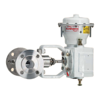
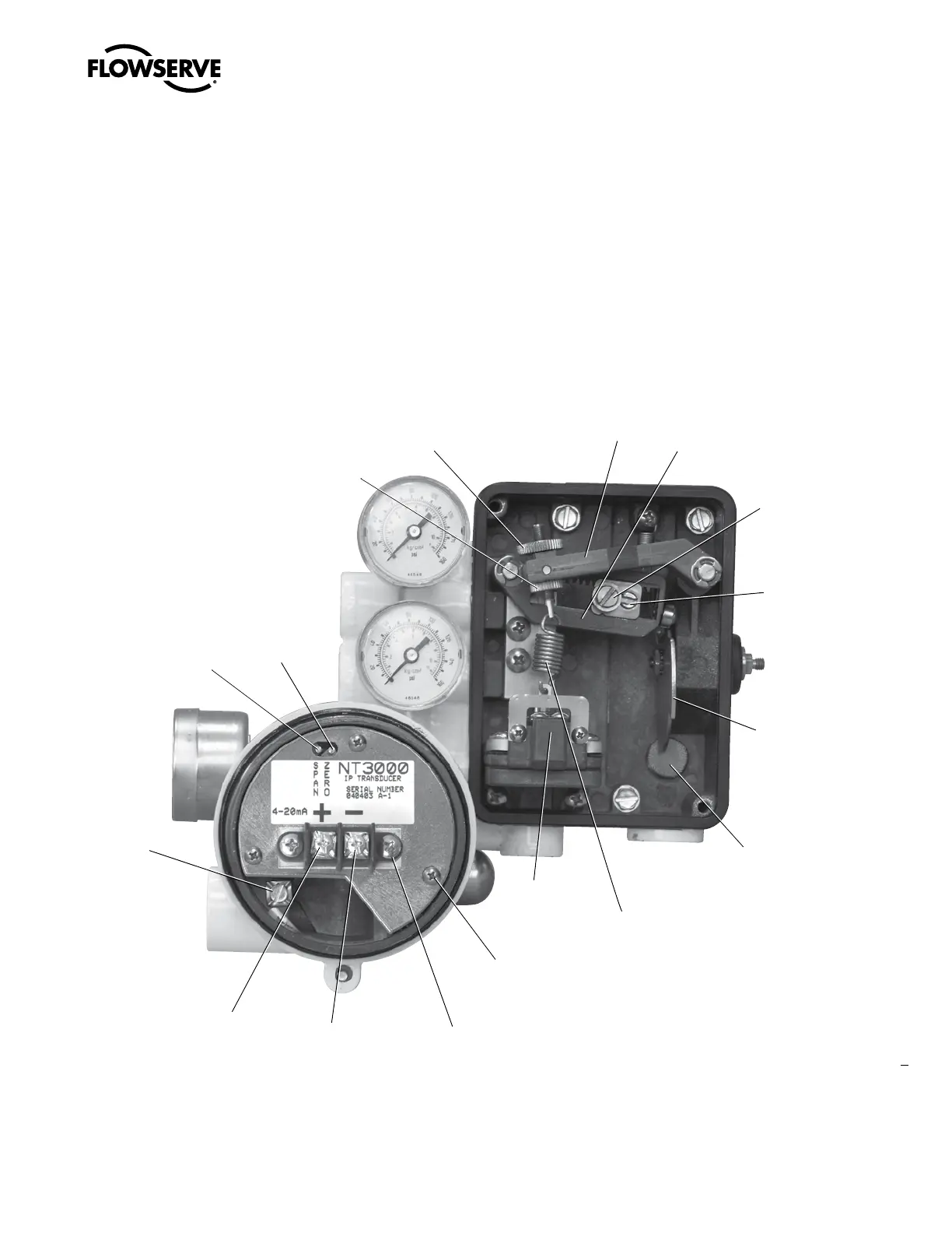
Figure 4 – Beta Positioner with NT 3000 Transducer
Zero Arm
Range Arm
Range
Adjustment
Locking
Screw
Range
Adjustment
Gear
Cam
Vent Screen
Feedback
Spring
Instrument
Signal
Capsule
Mounting
Screws
Terminal Block
Current Loop
Termination (-)
Current Loop
Termination (+)
Grounding
Screw
Span
Adjustment
Zero
Adjustment
Zero Adjustment
Locking
Knob
Zero Adjustment Knob
7. Remove the “Factory Calibrated” sticker from the pressure modu-
lator cover (8). Turn the setscrew (6) until the pressure indicated
on the pressure gauge on the NT 3000 transducer is 2.0 psi
(±0.20 psi). This is the correct pressure modulator adjustment.
8. Disconnect the air supply pressure to positioner.
9. Remove the rod plugging the pressure sensor port.
10. Reconnect the pressure modulator electrical connector to the
bottom of the circuit board.
11. Reinstall the circuit board by engaging the pressure sensor tube
and pressing it straight into the housing. Be careful not to damage
the pressure sensor O-ring or pinch the modulator connector wires
while installing the circuit board. Apply thread locking compound to
the three circuit board screws and replace.
12. Reinstall the housing cover and reconnect the air supply pressure.
13. Check the span and zero calibration.
 Loading...