Valtek GS General Service Valve FCD VLENIM0300-00-A4 08/14
13
flowserve.com
After these requirements are confirmed the control valve can be maintained and repaired.
Description of the Procedure
1. Disconnect the air supply from the actuator and / or
assembled accessories.
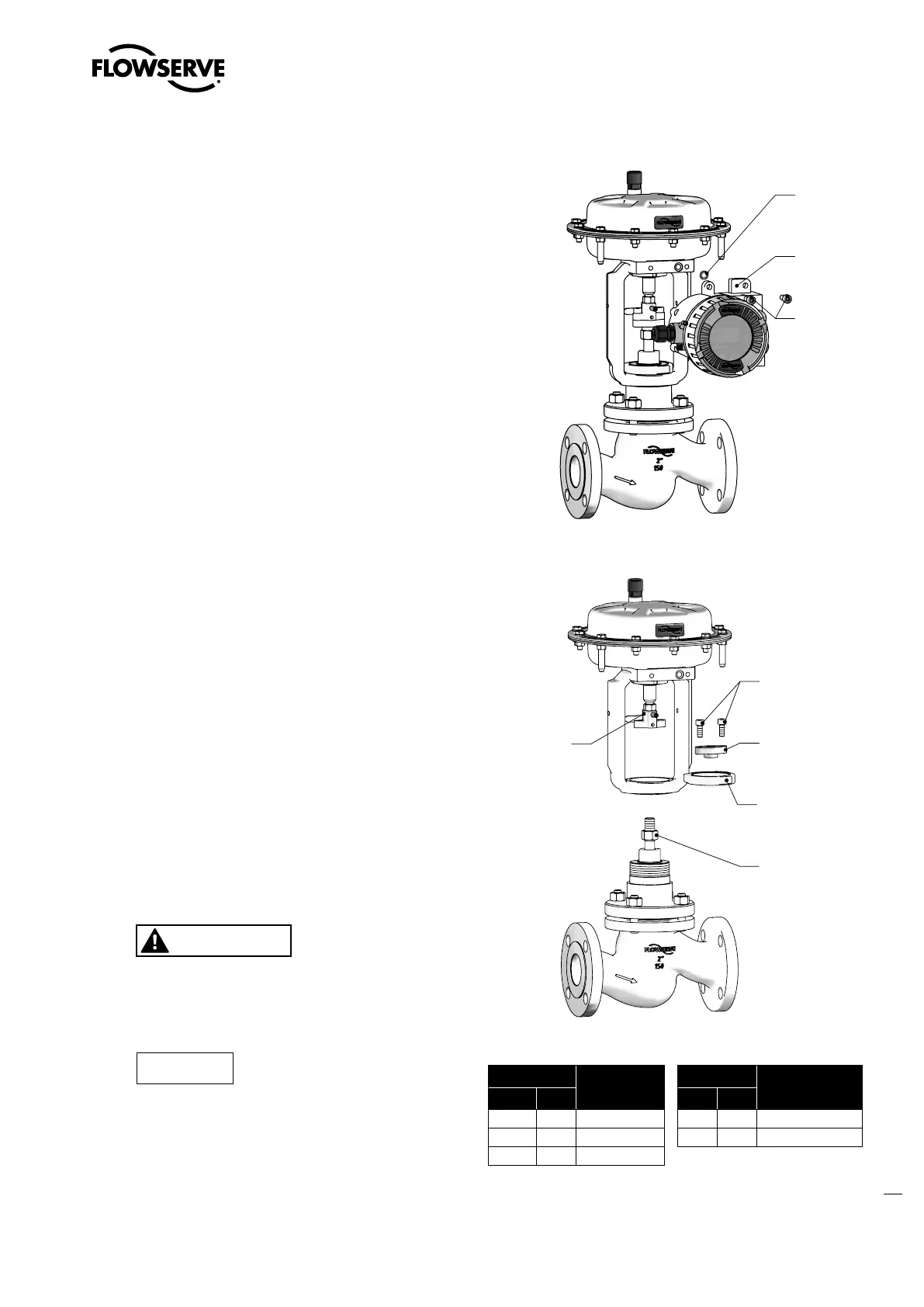
2. Disassemble the positioner from the valve as neces-
sary (See Figure 7: Remove the positioner).
3. Move the actuator to the open (retracted) position.
4. Turn the lock nut (113) clockwise to loosen. Keep up-
per coupling (249) from turning by securing with a
wrench (See Figure 8: Remove the actuator).
5. Turn the cap screws (240) counter clockwise to loosen.
6. Turn the yoke lock nut (76) counter clockwise to
loosen.
7. Lift off and store the actuator safely.
8. Place the valve body assembly on a table for disas-
sembly.
Disassembly instructions of the valve body
assembly
(standard or extended bonnet design).
1. Turn the bonnet nuts (114) counter clockwise to loosen
(See Figure 9: Disassemble / Reassemble the valve).
2. Turn the packing follower (80) counter clockwise to
loosen.
3. Remove the Belleville springs (109).
4. Remove the upper stem guide (87).
5. Place the Ring Nut Tool (See Section 16: Special Tools)
on the stem (50) and turn slowly.
WARNING
Crushing hazard ! Lifting
the bonnet and plug from
the control valve involves personal physical risk by
falling parts.
Please exercise caution.
NOTICE
Exercise care with a pressure bal-
anced plug design. While removing
the pressure balanced plug the cage may stick to the
plug head then become detached while lifting the plug
and stem out of the valve. Secure the cage as you re-
move the plug and stem.
O-ring
Positioner
Figure 7: Remove the positioner
240
345
76
113
249
Figure 8: Remove the actuator
Item
Part
Item
Part
WW
1)
EU
2)
WW EU
76 5.10 Yoke lock nut 249 5.3 Upper coupling
113 5.2 Lock nut 345 5.1 Lower coupling
240 5.5 Cap screw
Table 10: Coupling parts identification
1)
WorldWide
2)
European Union