INST 385 E35 SALT CHLORINE GENERATOR (10-2018)
SAVE THESE INSTRUCTIONS
DIRECTIONS FOR USE:
INSTALLATION
The E35 Salt Chlorine Generator control has a rating of IP23 enabling it to be installed outdoors. Regulations require
that the control is not allowed to be located within 3 m (10 ft.) of the pool water.
The E35 Salt Chlorine Generator Control should be installed in a well-ventilated position ideally away from direct
sunlight. Ensure that the unit is not located near pool chemicals as fumes may damage the control.
When installing the control on a post, first attach a flat waterproof panel at least 300 mm (12 in) wide by 500 mm (20 in)
long. Make sure the control is located centrally on the panel and sits flat.
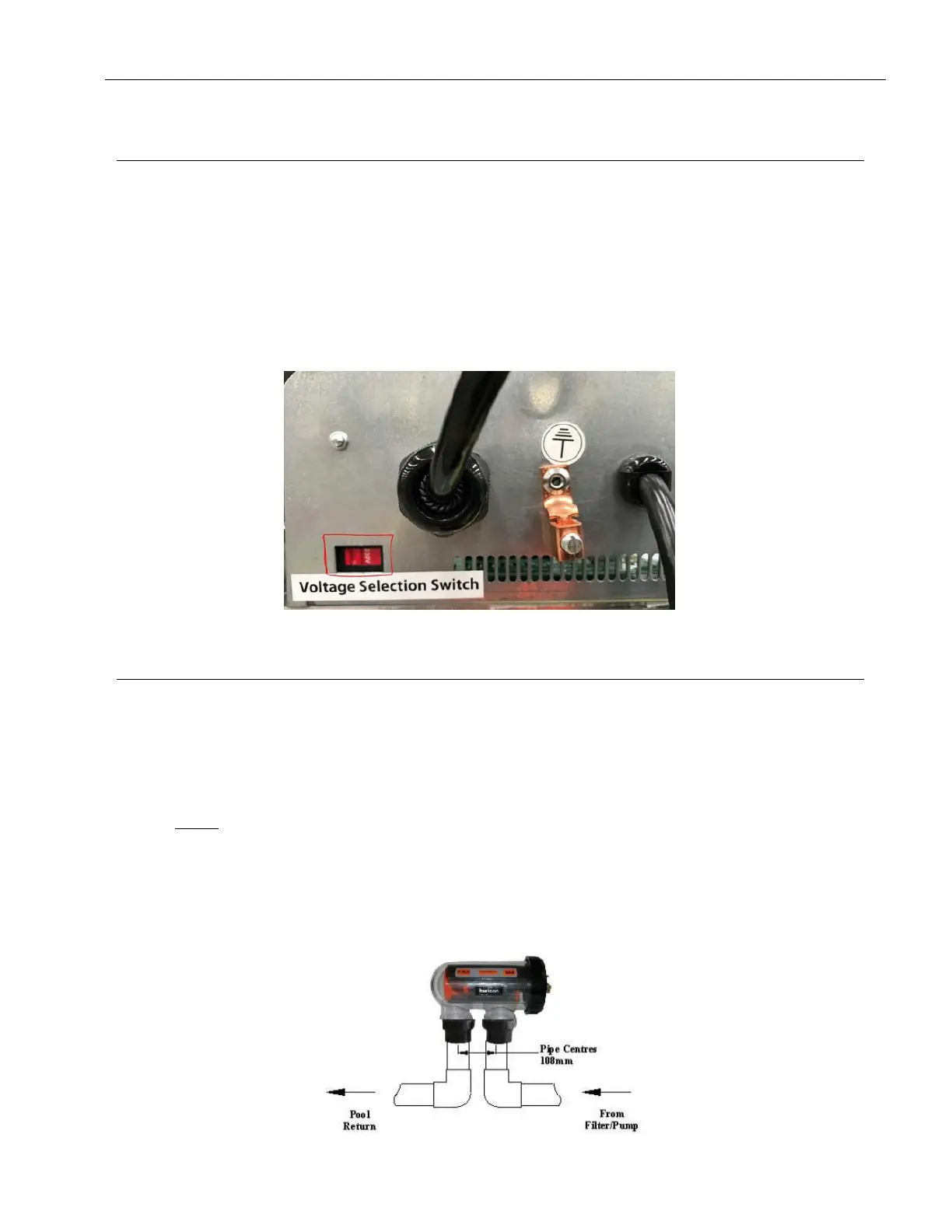
Electrical connection can either be 230 V or 115 V - 10Amp. The AstralPool E-Series is factory set at 230 Volts.
To change the input voltage, simply locate the switch, located at the lower left corner on the controller and slide the
switch to
the right until 115 V wording is visible. It is now set to 115 V input voltage.
CELL INSTALLATION
The Salt Chlorine Generator Cell must be located last in the pipe work just prior to the return to the pool. If valves are
installed between the Salt Chlorine Generator Cell and the pool outlet, it is essential that they cannot deadhead the
pump. If
the pressure in the cell exceeds 350 kPa (50 PSI) and/or the water temperature exceeds 40º C (104º F), the
Cell may fail.
WARNING: Never install the cell before the pump or heater.
The Cell MUST be installed with the barrel unions underneath (water connections pointing downwards) and the cell
should be
horizontal. 50 - 38 mm (2 - 1 ½ in) fittings have been provided. Use a 50 - 38 mm (2 - 1 ½ in) high pressure
PVC pipe and glue into the 50 - 38 mm (2 - 1 ½ in) barrel union tails. Make sure that the O-rings are correctly fitted and
the unions are tightened firmly.
Direction of flow through the Cell is critical – unit must be plumbed with the water entering the cell at the end closest
to the terminal connections (as indicated by flow direction label mounted on cell)