114, 115, and 117
Users Manual
4
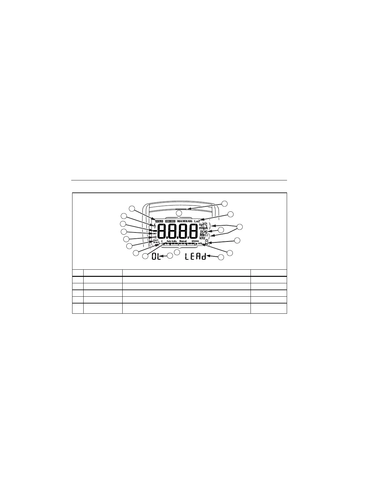
Display
VoltAlert
11
7
17
18
12
13
14
9
6
5
4
3
2
1
16
15
8
10
edy02f.eps
No. Symbol Meaning Model
A w The Meter is in the VoltAlert™ non-contact voltage detect mode.
117
B s The Meter function is set to Continuity.
114, 115, & 117
C R The Meter function is set to Diode Test
115 & 117
D O Input is a negative value.
114, 115, & 117
E
Y
X Unsafe voltage. Measured input voltage ≥30 V, or voltage
overload condition (OL).
114, 115, & 117
Shop for Fluke products online at:
1.888.610.7664
www.MyFlukeStore.com