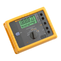
7 Fluke Corporation 1623 and 1625 GEO Earth Ground Testers
Electrical measurement specifications
Intrinsic error or influence
quantity
Reference conditions or specified
operating range
Designation
code
Requirements or test in
accordance with the relevant
parts of IEC 1557
Type
of test
Intrinsic error Reference conditions A Part 5, 6.1 R
Position Reference position ± 90° E1 Part 1, 4.2 R
Supply voltage At the limits stated by the
manufacturer
E2 Part 1, 4.2, 4.3 R
Temperature 0 °C and 35 °C E3 Part 1, 4.2 T
Series interference voltage See 4.2 and 4.3 E4 Part 5, 4.2, 4.3 T
Resistance of the probes and
auxiliary earth electrodes
0 to 100 x R
A
but b 50 k7 E5 Part 5, 4.3 T
System frequency 99 % to 101 % of the
nominal frequency
E7 Part 5, 4.3 T
System voltage 85 % to 110 % of the nominal voltage E8 Part 5, 4.3 T
Operating error Part 5, 4.3 R
A = intrinsic error
En = variations
R = routine test
T = type test
Measuring
Range Display Range Resolution Instrinsic Error Max. Operating Error
0.020 7 to 0.001 7 to 2.999 7 0.001 7 ± ( 2 % of rdg + 2 digit ) ± ( 5 % of rdg + 5 digit )
300 k7 3.00 7 to 29.99 7 0.01 7
30.0 7 to 299.9 7 0.1 7
0.300 k7 to 2.999 k7 1 7
3.00 k7 to 29.99 k7 10 7
30.0 k7 to 299.9 k7 100 7
Measuring time typ. 8 sec. with a fixed frequency
30 sec. max. with AFC and complete cycle of all measuring frequencies
Additional error because of probe-and auxiliary earth
electrode resistance
Measuring error of RH and RS typ. 10 % of R
E
+ R
S
+ R
H
Max. probe resistance b 1 M7
Max. auxiliary earth electrode resistance b 1 M7
Automatic check if error is kept within the limits required by IEC61557-5.
If after a measurement of probe-, auxiliary earth electrode- and earthing resistance, a measurement error of higher than 30 % is assumed because of the influencing
conditions (see diagram), the display shows a warning symbol
!
and a notice that R
S
or R
H
are too high.

 Loading...