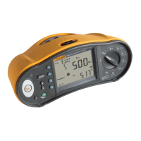
Electrical Installation Tester
Specifications
85
RCD Tripping Indicator
The RCD symbol switches on as a “good test” indicator when testing the RCD trip time
or RCD trip current if the trip time meets the following conditions:
RCD Type I
∆ N
Trip Time Limits
G x 1 Less than 300 ms
S x 1 Between 130 ms and 500 ms
G x 5 Less than 40 ms
S x 5 Between 50 ms and 150 ms
RCD Tripping Time (
Δ
T)
Test Function
RCD Current Selection
10 mA 30 mA 100 mA
[1]
300 mA
[1]
500 mA
[1]
1000 mA
[2]
Var
[3]
x ½, 1
• • • • • • •
x 5
• • •
Ramp
• • • • • • •
Auto
• • •
Mains voltage 100 V – 265 V ac, 45/66 Hz
[1] Type B RCDs require mains voltage range of 195 V – 265 V.
[2] Type AC RCDs only.
[3] Type A RCDs are limited to 700 mA, not available for Type B RCDs.
Current
Multiplier
RCD Type
[1]
Measurement Range
Trip Time Accuracy
Europe UK
x ½ G 310 ms 2000 ms
±(1 % Reading + 1 ms)
x ½ S 510 ms 2000 ms
±(1 % Reading + 1 ms)
x 1 G 310 ms 310 ms
±(1 % Reading + 1 ms)
x 1 S 510 ms 510 ms
±(1 % Reading + 1 ms)
x 5 G 50 ms 50 ms
±(1 % Reading + 1 ms)
x 5 S 160 ms 160 ms
±(1 % Reading + 1 ms)
[1] G – General, no delay / S – Time delay

 Loading...