Performance Verification
3.7 Voltage Inputs 3
3-7
6. Fluke 433/434: check for a current readout A rms between 985 ... 1015 A (tolerance
10 + 5 A = 15 A).
Fluke 435: check for a readout between 990 ... 1010 A (tolerance 5 + 5 A = 10 A).
(Voltage readout V rms must be approx. 0 V at A/L1, B/L2, C/L3 and 172 V at N
inputs, frequency approx. 60.00 Hz, Analyzer in DEMO mode).
7. Set the Calibrator to 0 Hz, 0 V and then to OPR.
8. On the Analyzer check for a current readout A rms between 0 ... 5 A.
3.6.2 Bandwidth check of current channels (*)
Is an optional test. Proceed as follows:
1. Set the Calibrator to 1 V, 60 Hz and OPR.
2. The current channels must be checked one by one. Use the Calibrator’s edit field
function (5500A: FIELD EDIT key, 5700A: AMPL/FREQ key) to adjust a readout of
1000 A for the current channel to be checked.
3. Increase the frequency to 3 kHz. Check for a readout of 945 A or more.
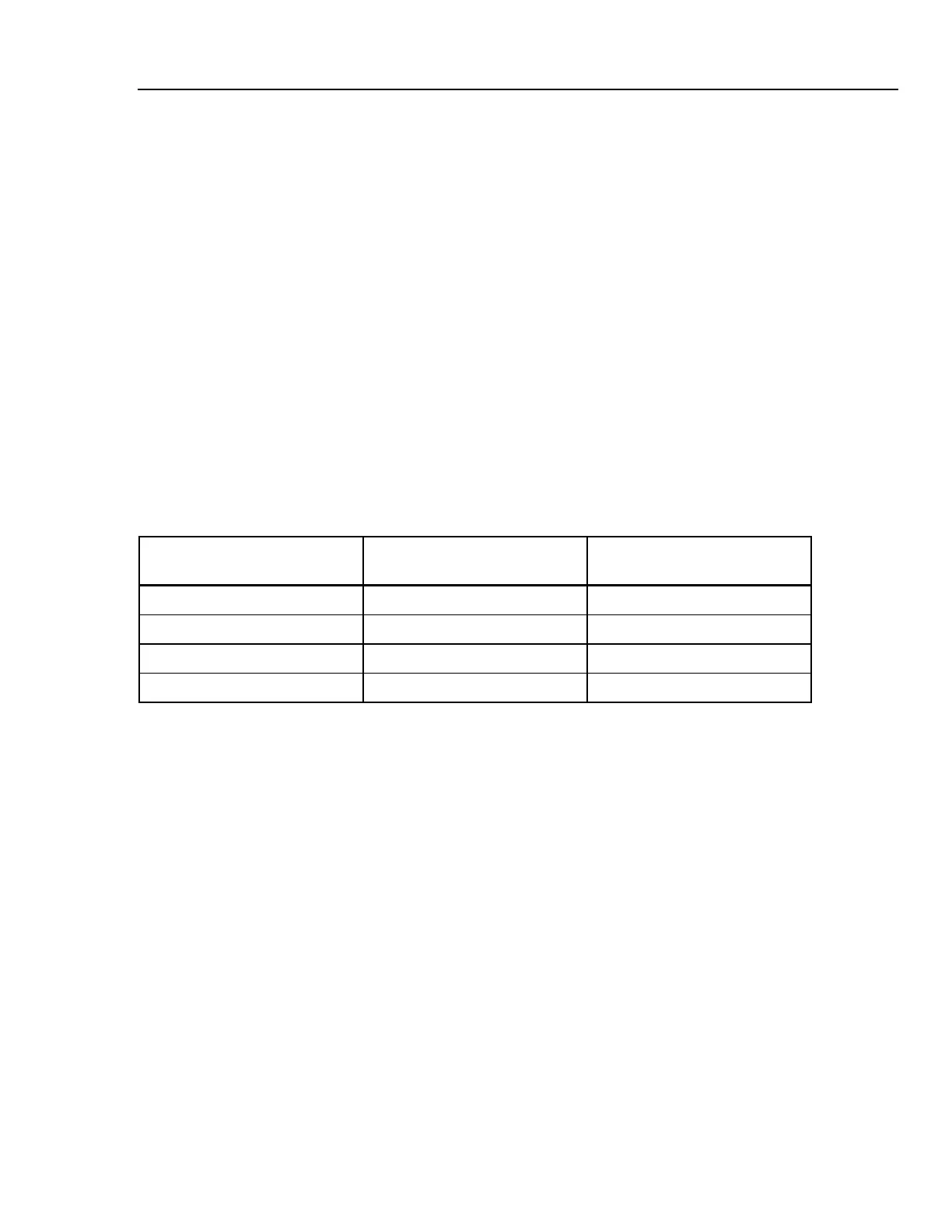
Table 3-1. Bandwidth Check of Current Channels
Current Channel to be verified Readout at 60 Hz (adjust
Calibrator with EDIT FIELD)
Readout at 3 kHz
Fluke 433/434/435
A/L1 1000 A 945 A or more
B/L2 1000 A 945 A or more
C/L3 1000 A 945 A or more
N 1000 A 945 A or more
4. Set the Calibrator to STBY.
5. Disconnect the leads from the current inputs.
6. Switch the Analyzer’s DEMO mode to OFF.
3.7 Voltage Inputs
3.7.1 Introduction
WARNING
Dangerous voltages will be present on the calibration source
and connecting cables during the following steps. Ensure that
the Calibrator is in standby mode before making any
connection between the Calibrator and the Analyzer.