Fluke 433, 434, 435
Service Manual
3-8
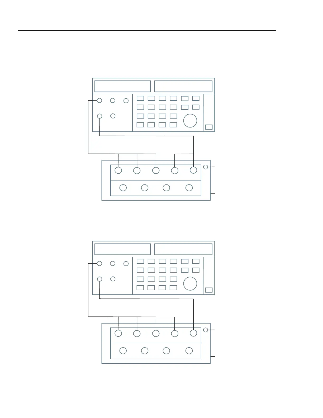
Proceed as follows:
1. To check the A/L1, B/L2, C/L3 inputs, connect the N input to Ground (See Figure 3-
3). N now will give zero reading.
A/L1
B/L2 C/L3
N
GND
A/L1
B/L2 C/L3
N
CALIBRATOR
POWER
DAPTER
BC 430
NALYZE
INPUT
BLOCK
LO
HI
NORMAL
Figure 3-3. Checking the A/L1, B/L2, and C/L3 voltage inputs
2. To check the N input, connect the N input with the adjacent C/L3 input. A/L1, B/L2,
C/L3 now will give zero reading. Refer to Figure 3-4.
A/L1
B/L2 C/L3
N
GND
A/L1
B/L2 C/L3
N
CALIBRATOR
POWER
DAPTER
BC 430
NALYZE
INPUT
BLOCK
LO
HI
NORMAL
Figure 3-4. Checking the N (Neutral) voltage input