Performance Verification
3.7 Voltage Inputs 3
3-15
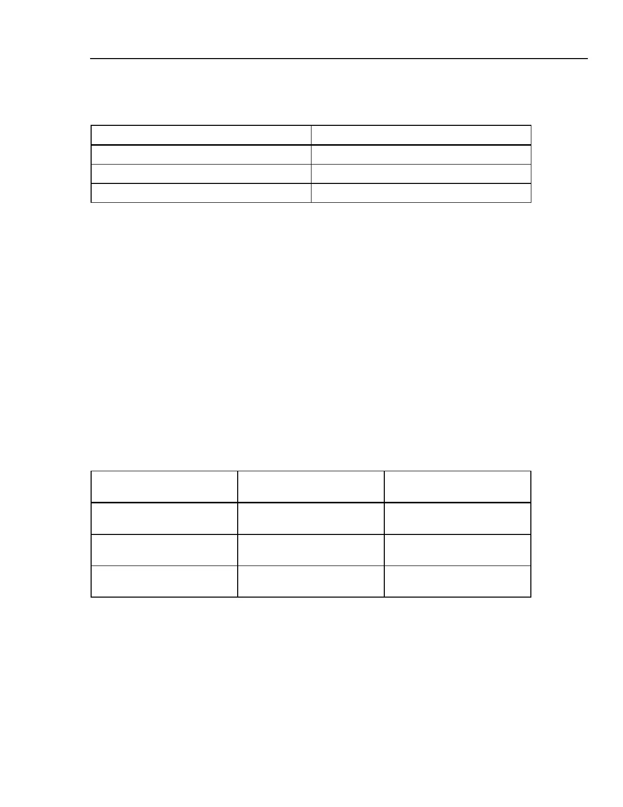
4. Check the 6 kV range according to the table below.
Table 3-11. Accuracy Check of Voltage Channels A/L1, B/L2, C/L3
Set Calibrator to Readout at Voltage Channels
0 Hz, 0 V, OPR 0 ... 10 V
400 V, 50 Hz, OPR 390 ... 410 V
1000 V, 50 Hz, OPR 990 ... 1010 V, 49.99 ... 50.01 Hz
5. Set the Calibrator to STBY.
Optional Test. Bandwidth Check of Channel A/L1, B/L2, C/L3 (*):
Note: for Fluke 435 you must use the Fluke 5700A Calibrator. This instrument is able to
generate 219.99999 V as a maximum at 3 kHz. Therefor a 50 Hz reference voltage of 215
V must be adjusted.
6. Set the Calibrator to 400 V (5700A: 215 V), 50 Hz and OPR.
7. Now check the voltage channels one by one. Use the Calibrator’s field edit function
(5500A: FIELD EDIT key, 5700A: AMPL/FREQ key) to adjust the Calibrator to an
Analyzer readout of 400 V / 215 V.
8. Increase the frequency to 3 kHz.
Fluke 434: check for a readout of 378 V or more.
Fluke 435: check for a readout of 204 V or more.
Check the channels according to the table below.
Table 3-12. Bandwidth Check of Voltage Channels A/L1, B/L2, C/L3
Voltage Channel to be verified Readout at 50 Hz (adjust
Calibrator with EDIT FIELD)
Readout at 3 kHz
A/L1 Fluke 434: 400 V
Fluke 435: 215 V
Fluke 434: 378 V or more
Fluke 435: 204 V or more
B/L2 Fluke 434: 400 V
Fluke 435: 215 V
Fluke 434: 378 V or more
Fluke 435: 204 V or more
C/L3 Fluke 434: 400 V
Fluke 435: 215 V
Fluke 434: 378 V or more
Fluke 435: 204 V or more
9. Set the Calibrator to STBY.
Accuracy Check of Channel N (Neutral):
10. Connect the N input with the C/L3 input (See Figure 3-4). A/L1, B/L2, C/L3 now
give zero reading.
11. Set the Calibrator to 0 Hz / 0 V and then to OPR.
12. Check for a voltage readout V rms between 0 ... 10 V.