Disassembling the Analyzer
5.1. Introduction 5
5-3
5.1. Introduction
This section provides the required disassembling procedures. The printed circuit
assembly removed from the Analyzer must be adequately protected against damage.
Warning
To avoid electric shock, disconnect test leads, probes and
power supply from any live source and from the Analyzer itself.
Always remove the battery pack before completely
disassembling the Analyzer. Only qualified personnel using
customary precautions against electric shock should work on a
disassembled unit with power on
5.2. Disassembly & Reassembly Procedures
5.2.1 Required Tools
To access all the assemblies, you need the following:
• Static-free work surface, and anti-static wrist wrap.
• #10 Torx screwdriver.
• Cotton gloves (to avoid contaminating the lens, PCA, and flat cable contacts).
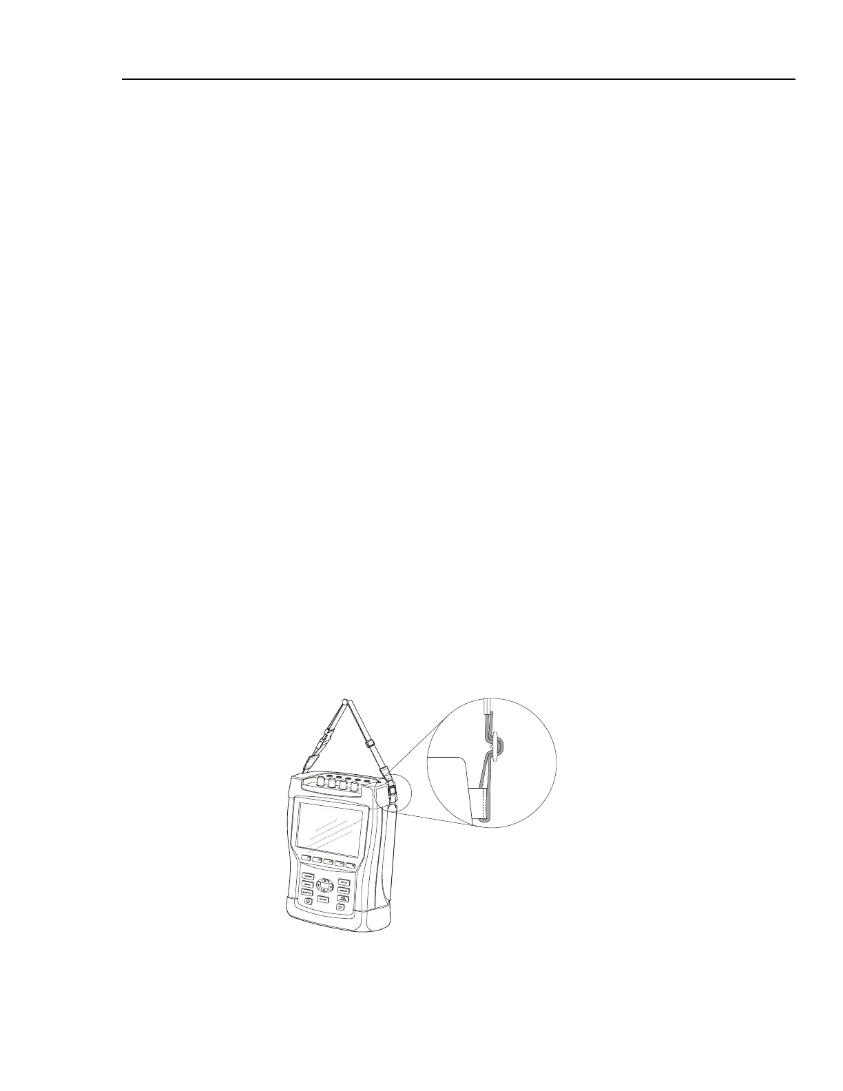
5.2.2 Removing the Tilt Stand & Hang Strap
Use the following procedure to remove the tilt stand and hang strap (Figure 5-6, item 15
and item 10).
1. Set the tilt stand to a 45-degree position respective to the Analyzer bottom.
2. The hinge consists of a circular raised rim in the tilt stand that is located over a
circular lowering in the bottom case. Pull sideward on the front edge of the tilt stand
until the hinge releases. Then rotate the stand to the rear to remove it.
3. The figure below shows how to remove and install the hang strap.
Figure 5-1. How to remove and fix the hang strap