Disassembling the Analyzer
5.2. Disassembly & Reassembly Procedures 5
5-7
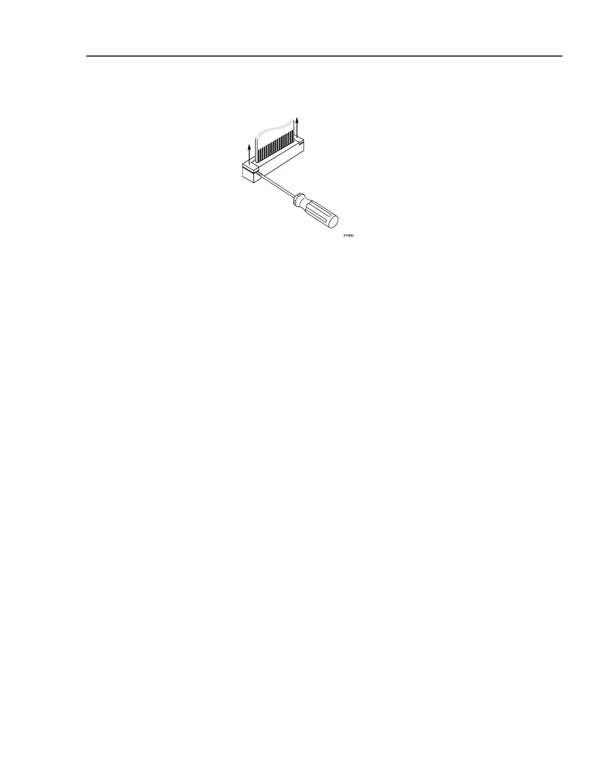
using a small screw-driver, see Figure 5-7. The latch remains attached to the
connector body.
ST8682.WMF
Figure 5-7. Flex Cable Connectors
3. Unplug the two-wire backlight cable.
Warning
If the battery pack or the power adapter is connected, the LCD
backlight voltage on the wire cable is 400V ! (when the Analyzer
is on).
4. Remove the two screws (item 19) that secure the Main PCA unit to the top case.
5. Gently unlock the flaps of the keypad foil (item 4) that are stuck on to the metal
shielding box.
6. Unlock the plastic clamps at the inputs side and remove the Main PCA unit.
5.2.6 Removing the Display Assembly
There are no serviceable parts in the display assembly. Referring to Figure 5-6, use the
following procedure to remove the display assembly.
1. Remove the main PCA unit (see Section 5.2.5).
2. Unscrew the four screws item 8.
3. Remove the display assembly (item 6) with its mounting frame (item 7).
To prevent finger contamination, wear cotton gloves, or handle the display assembly
by its edges.
4. Remove the display from the mounting frame.