5320A Users Manual Supplement
4/12 3
Change #5
On page 6-12, replace Table 6-8 with the following:
Table 6-8. High Test Current Ground Bond Source Limits
Nominal
Value
Required Standard
Calibrator/Multimeter
Current/Voltage
Uncertainty
DC Test
Current
R
gbr
Lower Limit
[1]
Upper Limit
[1]
25 m 0.5% 20 A R
disp
- 5 m R
disp
+ 5 m
50 m 0.2 % 10 A R
disp
- 5 m R
disp
+ 5 m
100 m 0.1 % 10 A R
disp
- 5 m R
disp
+ 5 m
330 m 0.1 % 5 A R
disp
- 7 m R
disp
+ 7 m
500 m 0.1 % 3 A R
disp
- 8 m R
disp
+ 8 m
1 0.1 % 2 A R
disp
- 10 m R
disp
+ 10 m
1.8 0.1 % 2 A R
disp
- 18 m R
disp
+ 18 m
[1] R
disp
= Displayed Value
Change #6
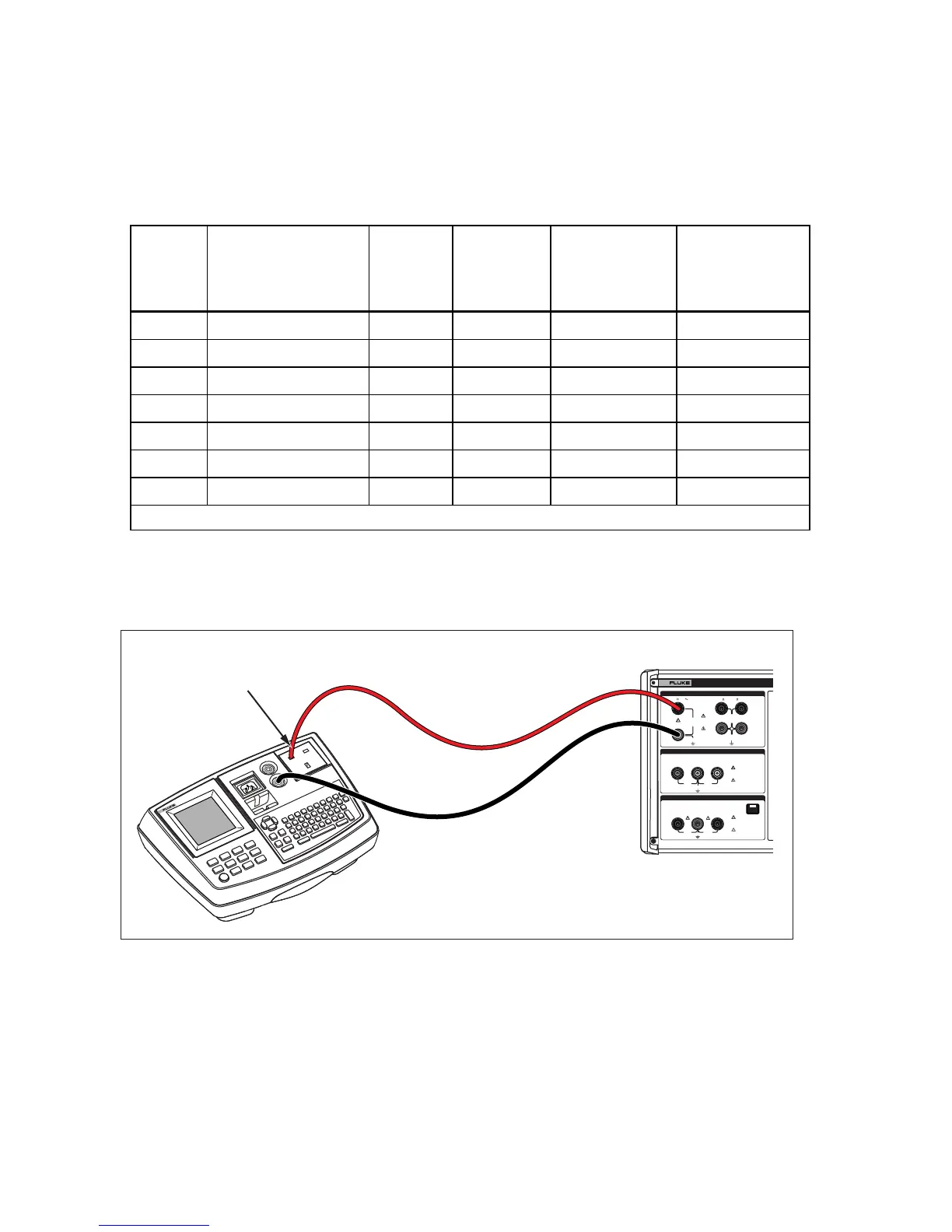
On page 7-17, replace Figure 7-14 with the following:
280V
RMS
MAX
280V
RMS
MAX
CAT I
1000V
CAT II
600V
RMS MAX
20V PK
30A
RMS
MAX
20V PK
LO
LO - SENSE
, HI ,
mA
V
1500V PK
MAX
50V PK
MAX
20V PK
20V PK
N
L
PE
L1 L2 L3HES
OUTPUT
Z
L
, Z
GND
,
RCD
HI
LO
HI
LO
METER
METER
5320A
MULTIFUNCTION ELECTRICAL TESTER CALIBR
V
A
COM
INPUT
6500 APPLIANCE TESTER
Fluke 5320A
Fluke 6500
Line Pin
Ehq039.eps
Figure 7-14. Touch Leakage Current Calibration on Fluke 6500
Change #7
On page 6-14, replace Step 4 with:
4. Set the multifunction calibrator to the same voltage as the voltage on the mains input of the
Calibrator (5320A). 115 V or 230 V for example. Set the multifunction calibrator frequency to
55 Hz.
 Loading...