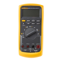
Digital Multimeter
Display
Display
.
8
7
7
5
6
4
3
2
1
13
14
15
9
11
12
10
AIK02F.EPS
No. Symbol Meaning
1
Continuity test.
2
Diode test.
3
Negative readings.
4
Y
Unsafe voltage. Voltage ≥30 V, or
volta
e overload
OL
5
AutoHOLD is enabled. Display holds
present reading until it detects new
stable input. Then the Meter beeps
and dis
la
s new readin
.
6
MAX , MIN,
AVG
MIN MAX AVG enabled.
Maximum, minimum, average, or
present reading.
7
nμ F, mVA,
Mke, kHz
Measurement units.
No. Symbol Meaning
8
DC, AC
Direct current, alternating current.
9
Low battery. Replace battery.
10
610000mV
All possible ranges.
11
Bar graph
Analog display.
12
Auto Range
Manual Range
The Meter selects the range with
the best resolution.
The user selects the range.
13
±
Bar graph polarity.
14
The input out of range.
15
WTest lead alert. Displayed when
the rotary switch is moved to or
from the mA or A position.
Error Messages
Replace the battery immediately.
In the capacitance function, too much electrical
charge is present on the capacitor being tested.
Invalid EEPROM data. Have Meter serviced.
Invalid calibration data. Calibrate Meter.

 Loading...