EasyManua.ls Logo

Fluke 845A - Section 1: Introduction and Specifications; Introduction; Electrical Specifications

Fluke 845A
14 pages
To Next Page IconTo Next Page
To Previous Page IconTo Previous Page
Loading...
845A
SECTION I
1-1.
INTRODUCTION
1-2.
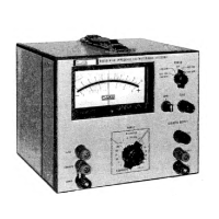
The Fluke
Model
845
High Impedance
Voltmeter-
Null
Detector allows
measurement of dc
voltages from
one
microvolt to
1000
volts dc in^l9
ranges.
When used
as a
null
detector on
the
100
millivolt range and
below,
the input impedance
is
10
megohms.
A linear recorder
output allows
the instrument
to be
used
for
production
testing and also as a
dc
amplifier
with
a
maximum
gain
of 120 db.
1-3. The
instrument consists
of
the line powered
Model
845A,
and the
line-battery-powered
Model
845AB.
The instruments are
half-rack
in size,
and are
equipped
with
resilient feet and
a
tilt-up bail
for field
or bench
use.
A single
instrument
may
be
mounted in
a
standard
19 inch rack by means of
metal handle rack
adapter
kit
881A-102, Two instruments may be
mounted side-by-
side in
a
standard
19 inch rack by
means of
metal handle
rack
adapter
kit 881A-103.
1-4. ELECTRICAL
SPECIFICATIONS
INPUT VOLTAGE
RANGE
1
microvolt
to
1000
volt dc end
scale in
nineteen
ranges,
using
XI and
X3 progression.
INPUT
RESISTANCE
100
megohms on
300
millivolt range and
above,
10
megohms
on 100
millivolt range and
below.
ACCURACY
±{2%
end scale + 0. 1
microvolt).
MAXIMUM METER
NOISE (Input Shorted)
RANGE
NOISE
(peak-to-peak)
1
microvolt
0. 20
microvolt
3
microvolt
0.
25 microvolt
10
microvolt
-
1000
volt
0. 30
microvolt
METER
RESPONSE
TME (to
90%
of
reading)
RANGE
TIME
1
microvolt
5 seconds
3
microvolt
3
seconds
10
microvolt
-
1000
volt
1-1/2 seconds
INPUT ISOLATION
Better than
1012
ohms at less
than
50%
relative
humidity
and
25°
C regardless of
line, chassis, or
recorder
grounding. Better than
lOlO
ohms
up to
80%
relative
humidity and 35°
C.
With
driven
guard, isolation im-
proves
by
at
least one order of
magnitude up to
10l3
ohms. Any
input terminal
may be
floated
1100
volts
off chassis
ground.
DC
COMMON
MODE
REJECTION
Better
than 160 db,
input
short-circuited,
80%
relative
humidity.
Better
than 140 db,
open-circuited,
50%
relative
humidity.
Better than 120
db,
open-circuited,
80%
relative
humidity.
AC
COMMON
MODE
REJECTION
(below 100
kHz)
100
volts rms
or 120 db
greater
than end
scale,
which-
ever is
less,
will effect
reading
less
than
2%
of
end
scale.
Input
open-circuited.
AC
NORMAL
MODE
REJECTION
(60
Hz and above)
AC
voltages 60
db
above end
scale
will
effect reading
less
than
2%
of end
scale.
Maximum ac
voltage
not to
exceed
750
volts
rms.
RECORDER
OUTPUT
0-1
volt,
one side
at chassis
ground;
linear
to
0.
5%
of
end scale.
Source
impedance,
5k
to 7.
5k. Response
time
is
approximately
half
that
of
the
meter,
therefore
noise
may
exceed
meter
noise by
6 db,
STABILITY OF
ZERO
Better than
0.
15
microvolt/hour.
Better than 0.
3
microvolt/day.
TEMPERATURE
COEFFICIENT OF
ZERO
Less than
0. 1
microvolt/®
C from
15° C to 35°
C.
Less
than
0.
2
microvolt/® C
from
0°C to
50®
C.
ZERO CONTROL RANGE
±5
microvolt
minimum.
OVERLOAD
PROTECTION
Up
to 1100
volts dc
may be
applied
on
any
range.
Typical
recovery
time is 4
seconds.
1-1

Related product manuals